Maintenance
1132−2/A1
Winterthur Gas & Diesel Ltd.
9/ 15
4.3 Bearing Shell No.2 to No. #
− Removal
CAUTION
Damage Hazard: Use only
the applicable tools. Do
not attach external
installations during the
removal procedure.
1) Make sure that the crankshaft is lifted
to 0.3 mm.
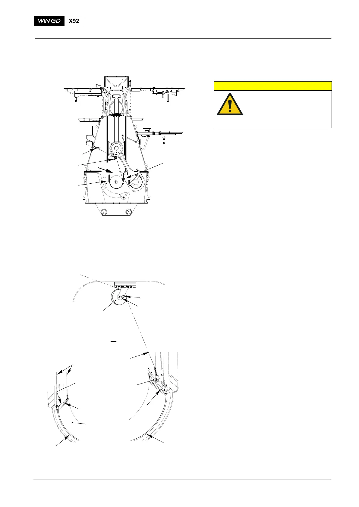
2) Attach the manual ratchet (H1, Fig. 1
and Fig. 14) to the column.
3) Attach the roller support 94117 to the
column above the main bearing. Make
sure that the spring clip (2) locks the
pin (3) in position.
4) Remove the Allen screws (1) from the
bearing girder.
5) Attach the hook of the manual ratchet
(H1) to the middle hole in the lifting
plate 94119A.
6) Attach the dismantling tool 94118C to
the bottom main bearing shell (3) with
four screws.
7) Put the wire ropes (4) around the
edges of the main bearing shell (3).
8) Attach the wire ropes to the to the lifting
plate 94119A.
2015
Main Bearing − Removal and Installation
Fig. 14
94118C
FUEL SIDE
2
3
EXHAUST SIDE
1
94119A
H1
I
H1
94117
94118C
I
94119A
WCH03015
94117
3
1
4
4
4
WCH03486