Maintenance1132−2/A2
Winterthur Gas & Diesel Ltd.
14/ 19
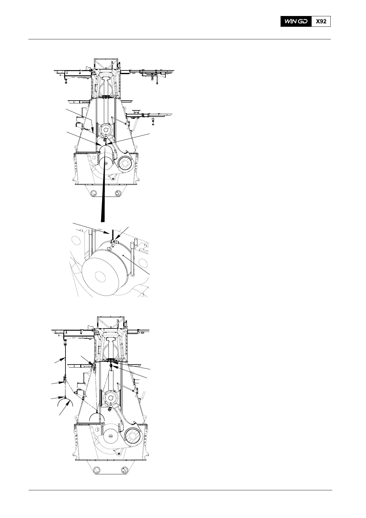
9) Operate the manual ratchet (H1,
Fig. 18) to turn the bearing shell (3)
until the center of the bearing shell (1)
is in a vertical position.
Note: If the bearing shell (1) does not
move freely during the removal
procedure, you must attach the
lifting plate (94119A, Fig. 17) to the
other side of the dismantling tool
(94118C). You must move the
bearing shell back to its initial
position and do the removal
procedure again.
10) Remove the dismantling tool (94118C),
lifting plate (94119A) and manual
ratchet (H1) from the bearing shell (1).
11) Attach the lifting device (94116A) to the
bearing shell.
12) Attach the manual ratchet (H1) to the
lifting device (94116A).
13) Use the manual ratchet (H1) to lift the
bearing shell.
14) Attach the eye bolt (94045-M56,
Fig. 19) to the top of the column.
15) Attach the chain block (H4) to the to the
eye bolt (94045-M56).
16) Attach the chain block (H4) to the
device (94116A) on the bearing
shell (1).
17) Take over the bearing shell (1) from
manual ratchet (H1) to chain
block (H4).
18) Attach the chain block (H2) and the
shackle (94019P) to the column.
19) Attach the chain block (H2) to the
device (94116A) and take over the
bearing shell.
20) Put sling 94039-015 around the gallery
and attach chain block 94017-029 (H3)
to the sling.
21) Attach the chain block (H3) to the lifting
device (94116A).
22) Operate the chain blocks (H2, H3) to
move the bearing shell (1) through the
opening in the column.
23) Lower the bearing shell (1) on to a
wooden underlay.
2016
Main Bearing Removal and Installation
Fig. 18
1
94116A
Fig. 19
H1
WCH03015
1
H1
94116A
Note: Some parts can look different
H3
94039−015
WCH03015
H4
94116A
94045−M56
H2
1
94019P
WCH03015