Maintenance
1132−2/A2
Winterthur Gas & Diesel Ltd.
15/ 19
3.
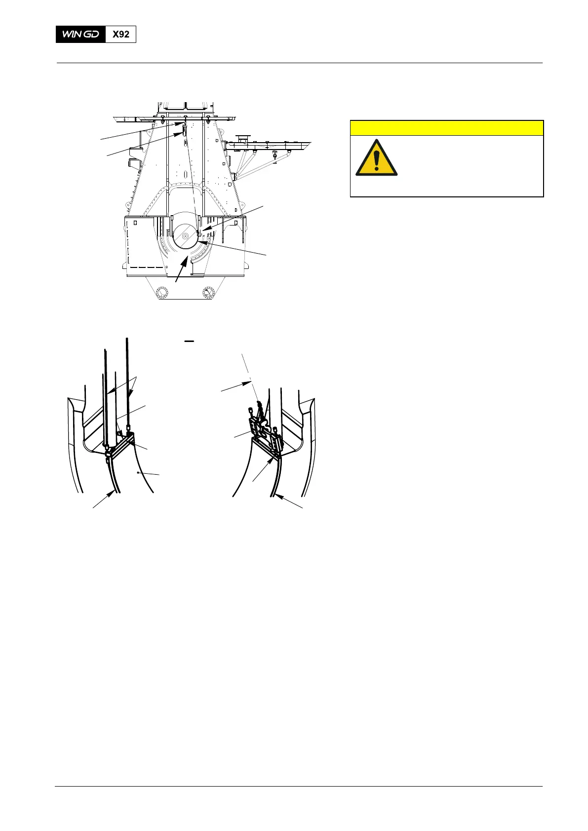
4.4 Bearing Shell No. 1
CAUTION
Damage Hazard: Use only
the applicable tools. Do
not attach external
installations during the
removal procedure.
Note: The bearing cover and the top
main bearing shell are removed.
The crank is on the exhaust side at
the TDC position.
1) Do the procedure to lift the crankshaft,
refer to paragraphs 4.1 and 4.2.
2) Make sure that the crankshaft is lifted
0.3 mm.
3) Attach the shackle (94019G, Fig. 20) to
the gallery.
4) Remove the two Allen screws (1) from
the top of the bearing shell (3).
5) Attach the chain block (H2) to the
shackle (94019G).
6) Attach the dismantling tool (94118B) to
the bearing shell (3).
7) Put the wire ropes (2) around the
edges of the main bearing shell (3).
Attach the wire ropes to the to the lifting
plate (94119).
8) Attach the chain block (H2) to the
middle hole in the lifting plate (94119).
9) Operate the chain block (H2) to move
the bearing shell to the top of the
crankshaft.
10) Remove the tool (94118B) and the
lifting plate (94119).
2016
Main Bearing − Removal and Installation
Fig. 20
FUEL SIDE
EXHAUST SIDE
WCH03015
H2
I
94019G
3
94119
94017−028
94118B
3
1
94119
H2
I
1
4
4
4
WCH03486