Maintenance1224−1/A1
Winterthur Gas & Diesel Ltd.
4/ 7
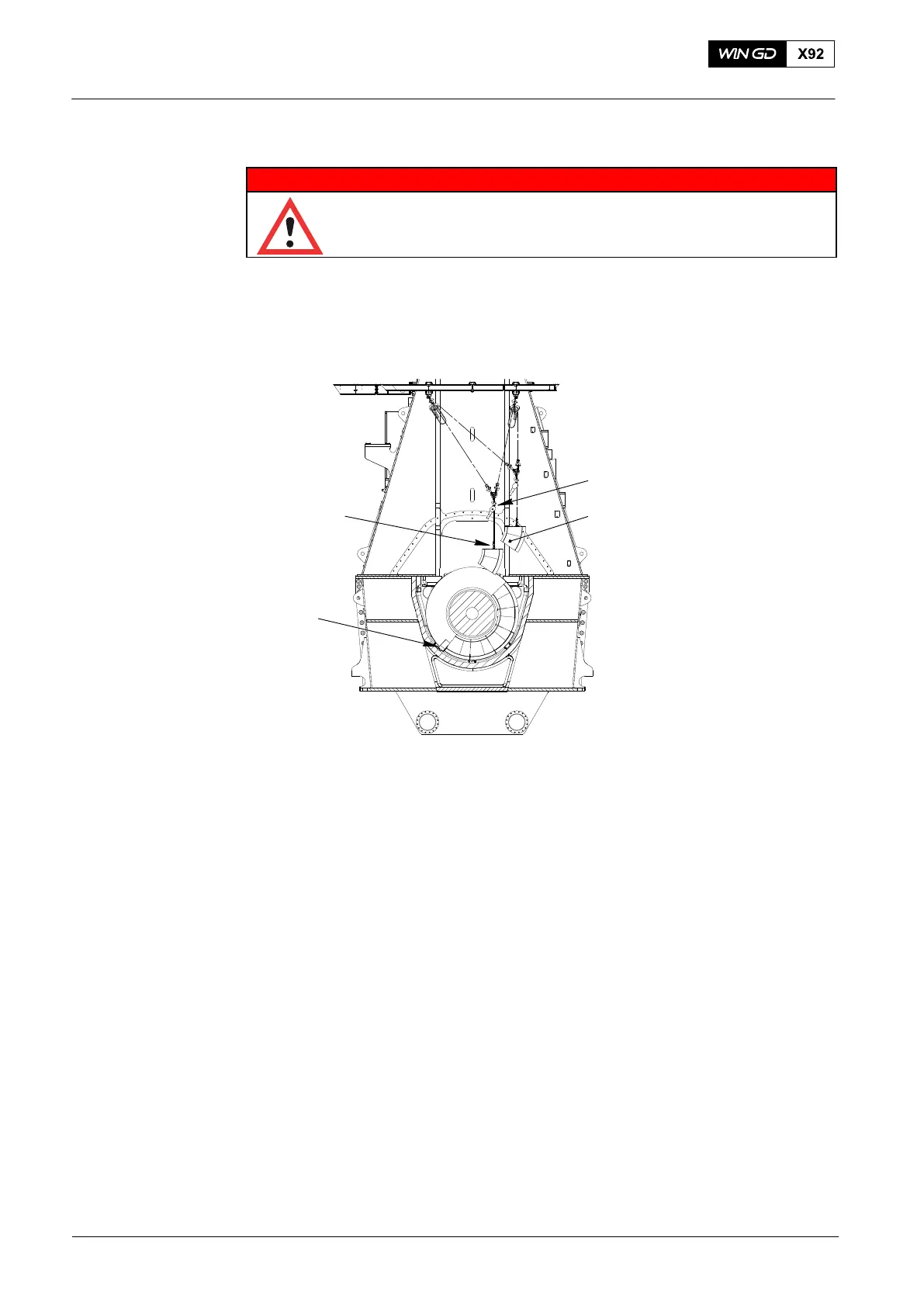
13) Attach the manual ratchet (H3, Fig. 4) to the eye bolt (94045-M12).
WARNING
Injury Hazard: Before you operate the turning gear, make sure
that no personnel are near the flywheel, or inside the engine.
14) Operate the turning gear to turn the crankshaft in the applicable direction.
Note: While the gear wheel turns, the carrier (94155A) moves the thrust pads.
The first thrust pad will come out.
Fig. 4
H3
94045−M12
94155A
WCH02906
1
15) Keep a light tension on the manual ratchet (H3, Fig. 4) while the thrust pad (1) moves
up.
16) Remove the thrust pad (1).
17) Move the thrust pad (1) to the exhaust side.
18) Lower the thrust pad on to a stable area.
19) Remove the manual ratchet (H3) and the eye bolt (94045) from the thrust pad.
20) Do step 12 to step 19 for the remaining thrust pads that you must remove.
Note: If some of the thrust pads are removed, the remaining thrust pads will
keep the crankshaft in position. If all thrust pads from the same side are
removed, e.g. all the astern pads, the crankshaft can move.
21) To prevent crankshaft movement, do step 22 and step 23.
22) Get a piece of hardwood that has the same dimensions as a thrust pad.
23) Put the hardwood in the position of the removed thrust pads.
2014
Thrust Bearing Pads − Removal and Installation