Maintenance1224−1/A1
Winterthur Gas & Diesel Ltd.
6/ 7
14) Remove the chain block and the eye bolt.
15) Install the three elastic bolts (3, Fig. 2) to the arbor supports (1, 5).
16) Lock the three elastic bolts (3) with wire (4) as shown.
17) Install the temperature sensors (1, Fig. 3) to the thrust pad (2) on the engine side.
18) Do a check of the clearances between the arbor supports and the thrust pads (see
0330−1 Clearance Table, Crankshaft and Thrust Bearing).
Note: When you replace new thrust pads (or thrust pads that have new metal),
you must make sure that the dimensions are the same as the adjacent
thrust pad(s).
When you replace a full set of thrust pads (or a full set of thrust pads that have new
metal), you must adjust the clearances to the original values (see 0330−1 Clearance
Table, Crankshaft and Thrust Bearing and 1203−1 Axial Clearance Check).
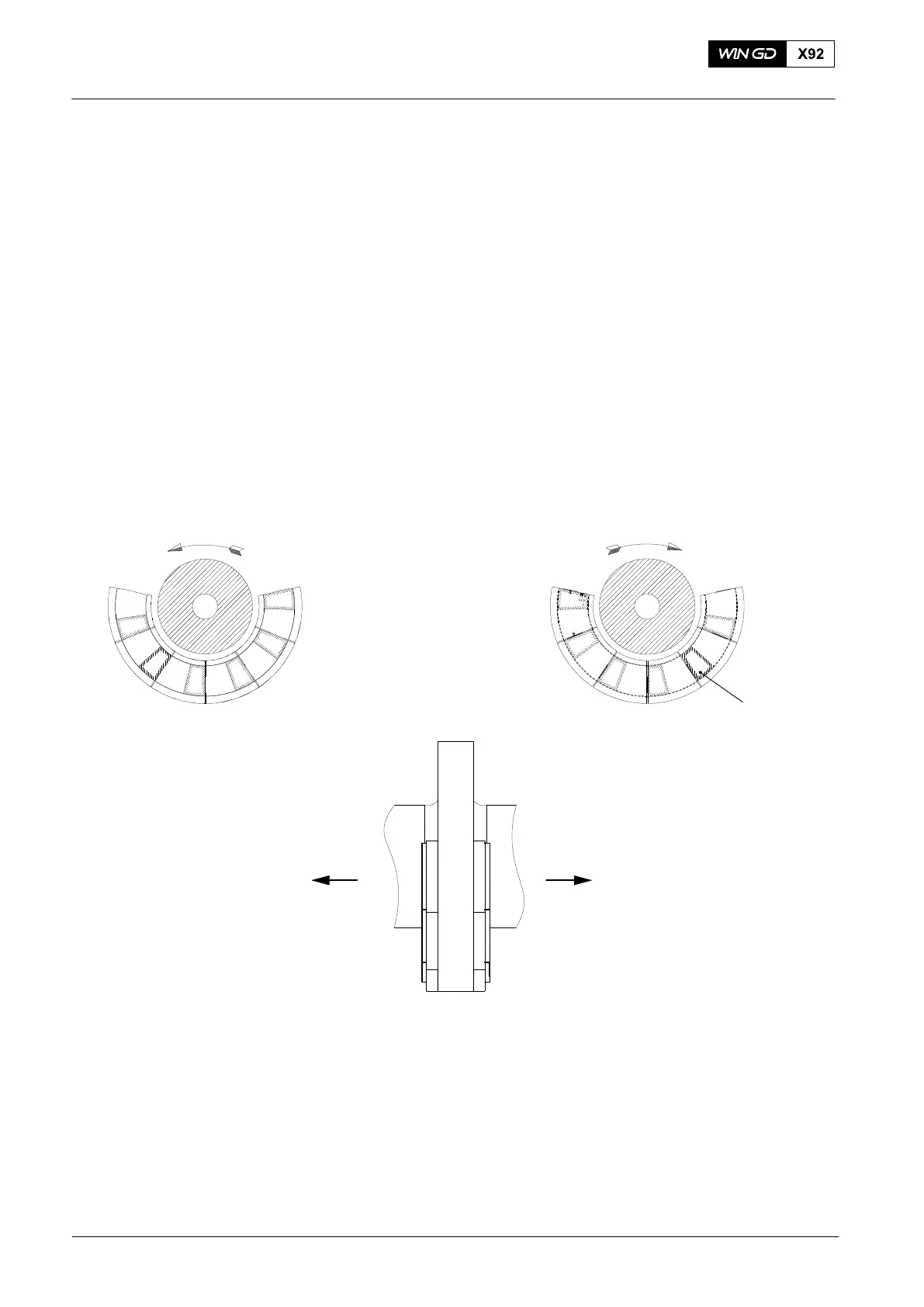
19) For the configuration of the thrust pads, see Fig. 6.
CONFIGURATION OF THRUST PADS WITH FIXED PITCH PROPELLER
AHEAD
ASTERN
SUPPORT SURFACE
VIEW FROM DRIVING END TO PADS
ON ENGINE SIDE
VIEW FROM DRIVING END TO PADS
AT DRIVING END
ENGINE SIDEDRIVING END
PROPELLER THRUST
AHEAD
PROPELLER THRUST
ASTERN
ENGINE WITH CLOCKWISE ROTATION
Fig. 6
WCH02906
2015
Thrust Bearing Pads − Removal and Installation