Maintenance2303−1/A1
Winterthur Gas & Diesel Ltd.
6/ 10
14) Put the two parts of the distance piece (94231B 12 mm height, Fig. 4) on the
gaskets (12, 14).
15) Put the four parts of the gaskets (12, 13) on the distance piece (94231B). Make sure
that there is an equal distance between the four parts.
16) Make sure that all horizontal spring dowel pins (18, Fig. 5) and the vertical spring
dowel pin (17) are installed.
Note: There is one hole for a vertical spring dowel pin on top of the scraper
rings (11).
17) Put the scraper ring (11) on the gaskets (12, 13). Make sure that there is an equal
distance between the four parts.
18) Make sure that the vertical spring dowel pin (17, Fig. 4) is installed.
19) Use the assembly tool (94233) to attach the tension spring (19) to the scraper
ring (11).
Note: There is no hole for a vertical spring dowel pin on the top of the scraper
ring (10).
1) Put the scraper ring (10) on the top of
the scraper ring (11). Make sure that
there is an equal distance between the
four parts.
2) Make sure that the vertical spring
dowel pin (17, Fig. 5) between the
scraper ring (10) and the scraper ring
(11) is correctly installed.
3) Use the assembly tool (94233) to
attach the tension spring (19) to the
scraper ring (10).
4) Remove the distance piece (94231B,
Fig. 6).
5) Remove the clamp ring (94231A).
6) Put the template (94231E) over the
assembled rings. Make sure that all
parts are in the correct position. If
necessary, correct the position.
7) Apply bearing oil to the piston rod and
the assembled rings.
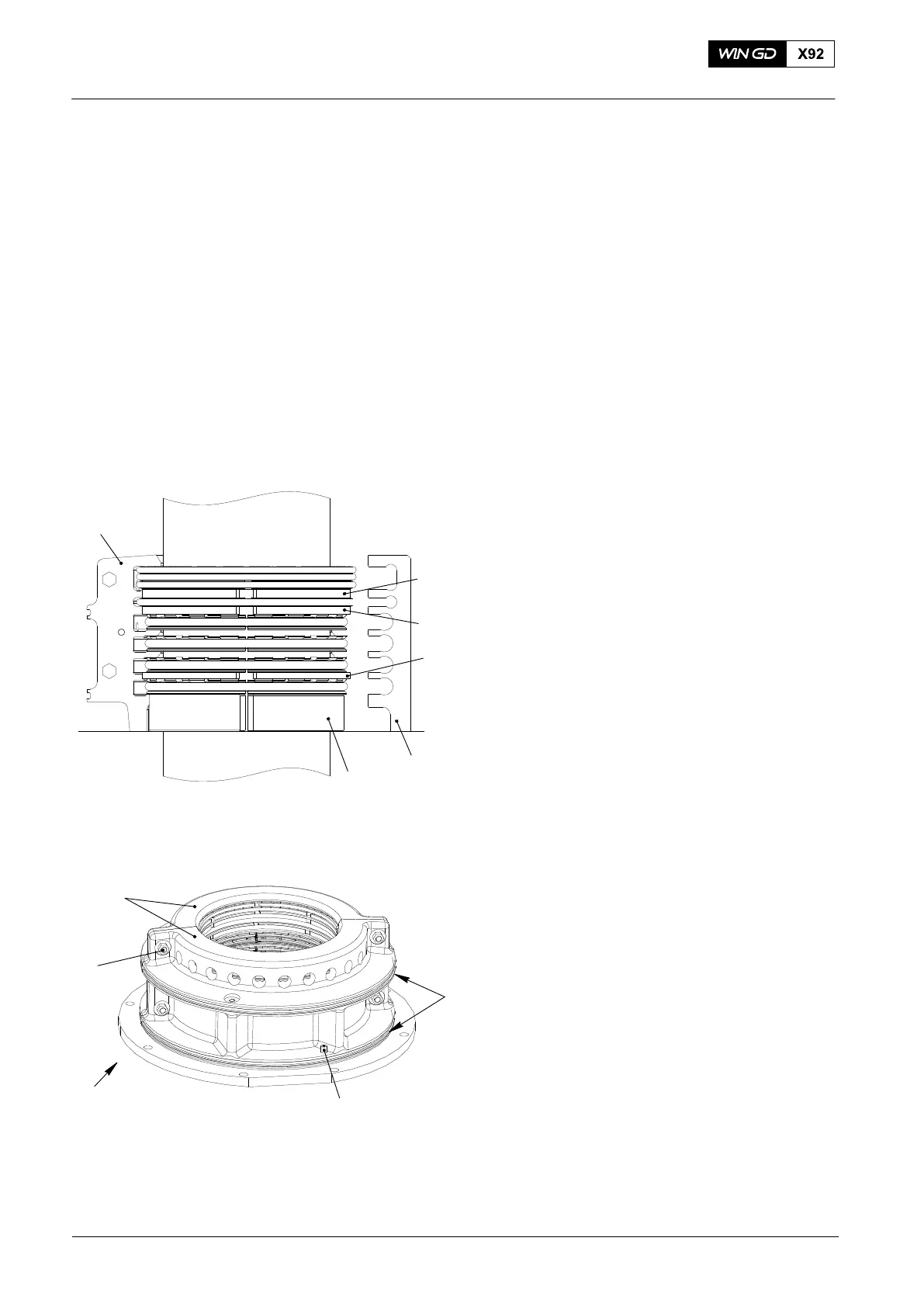
8) Push the two parts of the housing (2,
Fig. 7) over the assembled rings. Make
sure that the dowel pins (4) are
correctly installed.
9) Attach the four bolts (3) and nuts to the
housing (2).
10) Torque the bolts (3) to the value given
in 0352-2 Torque Values for Standard
Screws, paragraph 1.
11) Put oil on the O−rings (5).
12) Attach the O-rings (5) to the
housing (2).
2015
Remove, Disassemble, Measure Worn Parts, Assemble, Install
Fig. 6
94231E
94231A
94231D
94231C
94231B
2
Fig. 7
3
4
1
2
5
WCH02376