Maintenance
3326−1/A1
Winterthur Gas & Diesel Ltd.
7/ 13
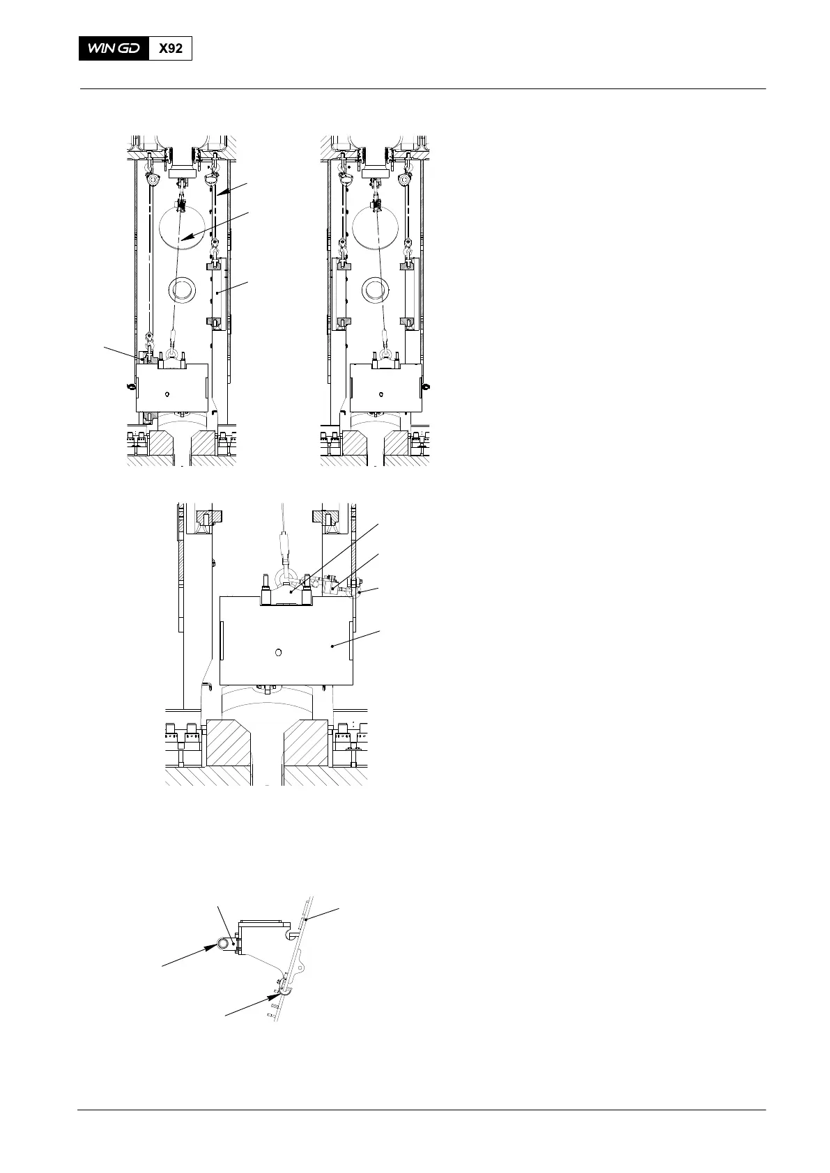
56) Use the spur-geared chain block
(94017-040, Fig. 15) to lift the guide
shoe (1 or 2).
57) Remove the chain (94325, Fig. 14), the
shackle (94019N) and manual ratchet
(94016-015).
58) Attach the chain chain (94325) the
shackle (94019N) and manual ratchet
(94016-015) to the other side od the
crosshead pin (1).
59) Do the steps 55) to 57) for the other
guide shoe.
60) When the crosshead (1, Fig. 16) is in
the first or last cylinder position, do the
steps 61) to 66).
61) Attach the lifting eye bolt (94045-M56)
to an applicable hole in the column.
62) Attach the manual ratchet (94016-015)
to the eye bolt (9045-M56) and to the
shackle of the lifting tool (94324).
63) Use the manual ratchet (94016-015) to
pull the crosshead pin from the guide
shoe.
64) Use the spur-geared chain block
(94017-040, Fig. 15) to lift the guide
shoe (1 or 2).
65) Remove the manual ratchet
(94016-015, Fig. 16) and the eye bolt
(94045-M56).
66) Attach the eye bolt (94045-M56) to the
other side of the column.
67) Do the steps 63) to 65) for the other
guide shoe.
68) Remove the manual ratchet
(94016-015) and the eye bolt
(94045−M56).
69) Attach the deviation pipe (94117B, Fig.
17) to the door frame.
70) Attach the deviation pipe (94117C) to
the support on the supply unit.
2015
Crosshead Pin − Removal / Installation / Clearance Checks
1
2
Fig. 15
94017-051
Fig. 16
94045-M56
94324
94016-015
1
94017-040
Fig. 17
94117B
94117C
Door Frame
Support
WCH03035