Maintenance3326−1/A1
Winterthur Gas & Diesel Ltd.
8/ 13
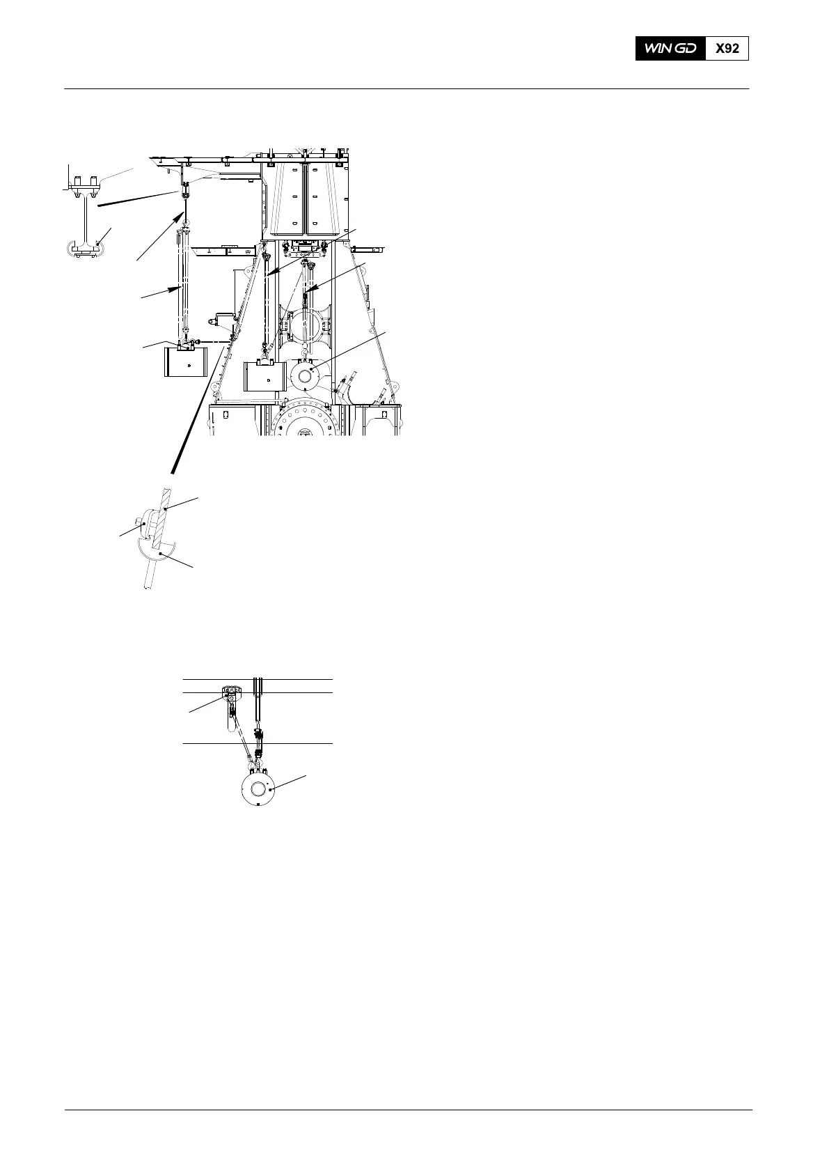
71) Attach the deviation pipe (94319, Fig.
18) to the support on the gallery.
Note: After removal or assembly work,
the deviation pipe (94319) has to
be removed from the engine.
72) Attach the sling (94039-057) to the
beam in the gallery.
73) Attach the spur-geared chain block
(94017-047) to the round sling
(94039-057).
74) Turn the crosshead pin (1) 90_.
Note: When you do the steps below,
keep the tension on the
spur-geared chain block
(94017-051).
75) Use the spur-geared chain blocks
(94017-051, 94017-040 and
94017-047) to carefully move the
crosshead pin (1) from the engine to
the fuel side.
76) Lower the crosshead on to an
applicable wooden underlay.
77) Remove the chains of the spur-geared
chain blocks (94017-051 and
94017-040) from the lifting device
(94324) on the crosshead pin (1).
Note: As an alternative, you can use the
spur-geared trolley (94015-008,
Fig. 19) to remove and to transport
the crosshead pin (1).
2015
Crosshead Pin − Removal / Installation / Clearance Checks
Fig. 18
94319
94017-047
94039-057
1
94017-051
94017-040
94117B
Door Frame
Clamp
94324
Fig. 19
1
94015-008
WCH03035