Maintenance
3326−1/A1
Winterthur Gas & Diesel Ltd.
9/ 13
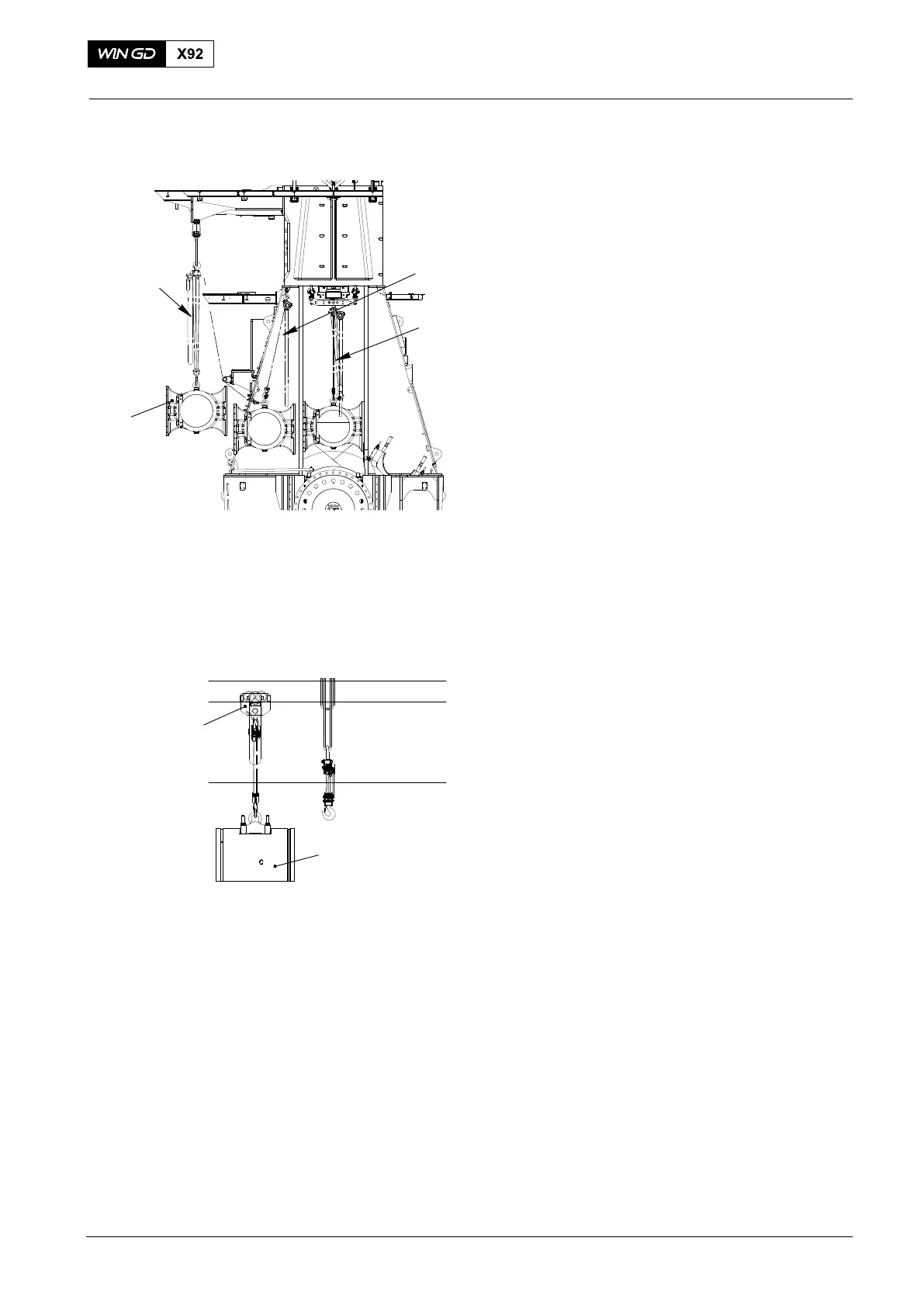
3. Guide Shoes − Removal
1) Record the positions of the guide
shoes. The shims of the guide shoes
can have different dimensions (0.3 mm,
0.5 and 1 mm thickness). This will help
you during the installation procedure.
2) Use the spur-geared chain blocks
(94017-040, Fig. 20) to lower the guide
shoe to the door frame.
3) Attach the two spur-geared chain
blocks (94017−051) to the eye bolts on
the guide shoe.
4) Apply a tension to the chains of the
spur-geared chain blocks (94017−051).
5) Attach the hooks of the spur-geared
chain block (94017-040) to the eye
bolts on the guide shoe.
6) Tighten the chain of the spur-geared
chain block (94017-040).
7) Move the guide shoe (1) through the
door frame as follows:
a) Tighten the manual ratchet that is
attached to the gallery. At the
same time, carefully loosen the
chain of the spur-geared chain
block (94017-040).
b) Lower the guide shoe (1) to an
applicable wooden underlay.
8) Do the steps 2) to 7) for the other guide
shoe.
Note: As an alternative, you can use the
spur-geared trolley (94015-008,
Fig. 21) to remove and to transport
the guide shoe (1).
2015
Crosshead Pin − Removal / Installation / Clearance Checks
Fig. 20
Fig. 21
94015-008
94017-051
94017-047
94017-040
1
1
WCH03035