Maintenance5551−1/A1
Winterthur Gas & Diesel Ltd.
8/ 11
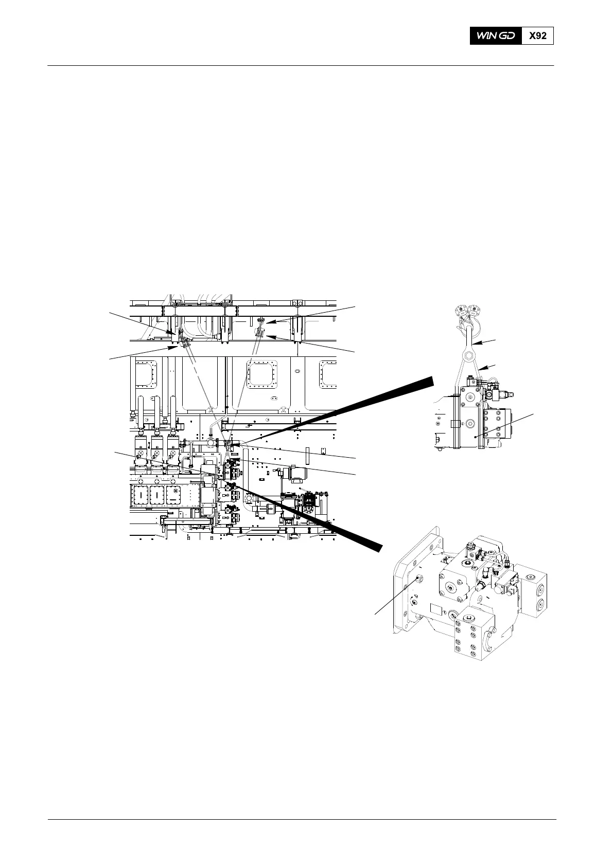
4) Put the sling (94039-002, Fig. 8) around the servo oil pump (1).
5) Attach the sling (94039-002) to the shackle (94019P).
6) Attach the spur-geared chain blocks 94017-004 (1, 2) to the shackle (94019P).
7) Use the spur-geared chain blocks (1, 2) together to lift the servo oil pump into a
position level with the supply unit.
Note: Do step 8) until the servo oil pump is in the correct location in the supply
unit.
8) Gradually increase the tension of the spur-geared chain block (1). At the same time,
decrease the tension of the spur-geared chain block (2).
9) Attach the servo oil pump (3) to the casing with the four nuts (4).
10) Remove the sling 94039-002 from the servo oil pump (4).
WCH03058
94017−004
94039−002
3
1
94017−004
2
94019P
94019P
94039−002
3
4
Fig. 8
2015
Servo Oil Pump − Removal and Installation