Maintenance
5556−1/A1
Winterthur Gas & Diesel Ltd.
13/ 18
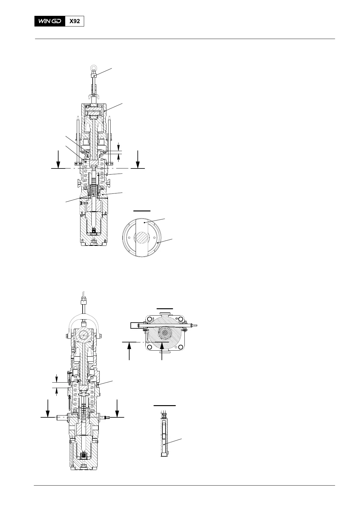
6) Lower the lower housing (1, Fig. 21) on
to the upper housing (3) until the spring
carrier (6) is approximately 10 mm to
20 mm above the spring (5).
7) Align the actuators (7) on the pump
plunger (4) with the slots in the
regulating sleeve (2).
8) Continue to lower the lower housing (1)
until the spring carrier (6) touches the
spring (5).
9) Remove the crane hook from the
spindle press (94551).
10) Remove the ring (94593A) and the
two-part ring (94593B).
11) Make sure that there is a clearance of
50 mm between the upper housing and
the lower housing (see Fig. 22).
12) Put the two Allen screws (1) in position
and tighten them simultaneously.
Torque them to 140Nm.
Fuel Pump: Disassemble, Assemble
2015
4
I I
I - I
10 mm to
20 mm
2
2
7
Fig. 21
1
3
6
5
94551
Fig. 22
WCH03053
I I
WCH03053
50 mm
1
IIII
I - I
II - II
1