Maintenance5556−2/A1
Winterthur Gas & Diesel Ltd.
2/ 4
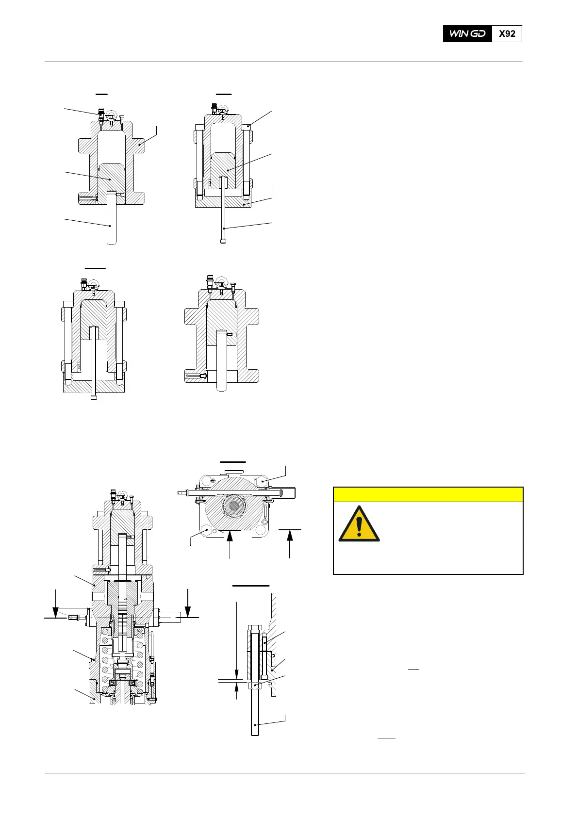
2. Hydraulic Ram −
Preparation
1) Open the vent screw (5, Fig. 2) and
push the piston (2) to the top of the
cylinder of the hydraulic ram 94595.
2) If you cannot move the piston (2) with
your hand, do step a) to step c):
a) Remove the push rod (4) (94595B
or 94595C) from the piston (2).
b) Attach the piston reset tool
(94595D) to the hydraulic ram
(94595) with two of the screws (1).
Note: The screws (1) are from the fuel
pump cover.
c) Use the spindle (3) to push the
piston (2) to the top of the
cylinder.
3) Remove the piston reset tool (94595D).
4) Put the short push rod (4) (94595B)
into the piston (5).
3. Hydraulic Ram −
Installation
1) Attach the hydraulic ram (94595, Fig. 3)
to the fuel pump with the twelve screws
(1).
CAUTION
Damage Hazard: There is
no support below the
housing. The bottom
housing can fall and cause
damage when the screws
are removed.
2) Hold the bottom housing (4) in position,
then remove the four bolts (5) from the
top housing (6).
3) Put the two screws (94595E) through
the bores of the flange in the top and
bottom housings (6, 4) in the positions
shown (view I−I).
4) Put the nuts (3) on the screws
(94595E).
5) Adjust the nuts (3) to get a minimum
clearance of between 10 mm to 15 mm
(view II−II
).
6) Remove the twelve screws (1).
2015
Fuel Pump: Removal of a Seized Pump Plunger
WCH02281
4
3
5
WCH02281
1
2
II
94595D
I
I
I - I
II
94595
3
6
1
2
WCH02365
014.181/06
5
94595
10 mm to 15 mm
II
4
Fig. 2
Fig. 3
I - I
II
94595
2
I I
I
II
94595E
WCH02365