Maintenance5556−2/A1
Winterthur Gas & Diesel Ltd.
4/ 4
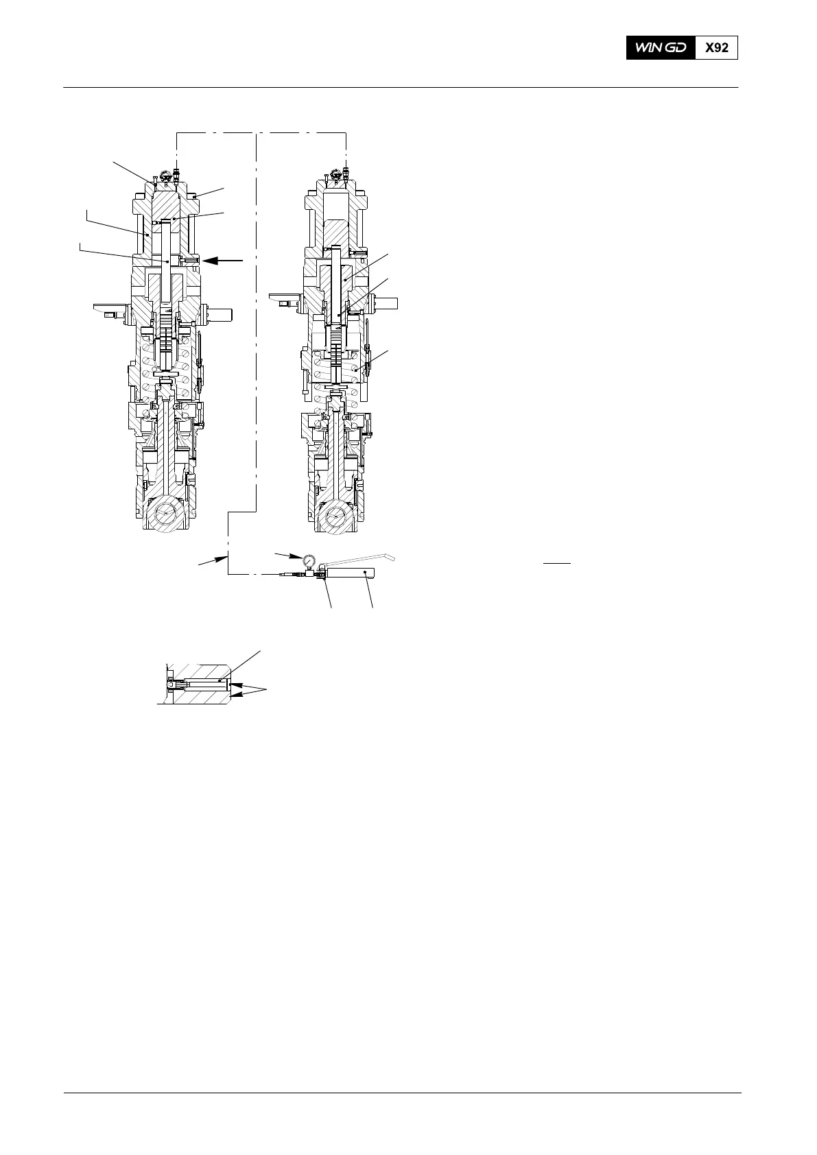
5. Removal with Tool
94595C
1) Remove the short push rod (94595B)
from the hydraulic ram 94595.
2) Put the long push rod (94595C, Fig. 5)
into the hydraulic ram 94595.
3) Install the hydraulic ram (94595) to the
fuel pump (see paragraph 3).
4) Connect the hydraulic ram (94595) to
the HP oil pump (see ).
5) Close the relief valve (4).
6) Open the vent screw (8).
7) Operate the HP oil pump until oil that
has no air flows from the vent screw
(8).
8) Close the vent screw (8).
Note: During the step below, make sure
that you keep a clearance of
between 10 mm and 15 mm
between the nuts (3, Fig. 3
view II−II
) and the bottom
housing (4).
9) Slowly operate the HP oil pump until:
D The compression spring (3, Fig. 5)
pushes the plunger (5) out of the
cylinder (1), or
D The indicator (5) is flush with the
housing. (This shows that the
piston is at the end of its stroke.)
10) Remove the screws (7)
11) Remove the hydraulic ram.
12) Remove the plunger (2).
13) Continue to disassemble the fuel pump
(see 5556−1).
Fuel Pump: Removal of a Seized Pump Plunger
2015
94595
94595C
94935
94932
4 94931
017.890/08
8
WCH02281
6
7
2
3
1
I
I
5
FLUSH
Fig. 5