Maintenance
6708−1/A1
Winterthur Gas & Diesel Ltd.
3/ 8
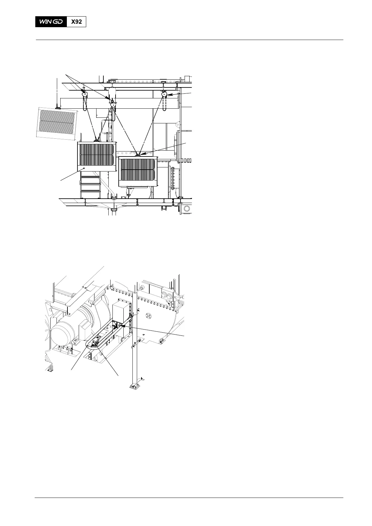
9) Attach the spur−geared chain block
(H2, Fig. 7) to the tool (94667).
10) Apply a light tension to the spur-geared
chain block (H2).
11) Loosen the spur−geared chain block
(H1). At the same time, tighten the
spur-geared chain block (H2) to move
the water separator under the engine
room crane.
12) Lower the water separator (1) to the
floor.
13) Remove the spur-geared chain blocks
(H1, H2) from the tool (94667) on the
water separator (1).
14) Attach the engine room crane to the
tool (94667) on the water separator.
15) Use the engine room crane to move the
water separator (1) to an applicable
area.
16) Remove the engine room crane from
the water separator.
17) Remove the tool (94667) from the
water separator.
2.2 Rear Water Separator
1) Attach the tool (94667, Fig. 8) to the
front of the water separator.
2) Install the holder (94667H) to the
middle of the housing on the receiver.
3) Attach the manual ratchet (H3) to the
holder (94667H) and the tool (94667).
2015
Water Separators: Removal and Installation
Fig. 7
Fig. 8
H1
H2
94667
WCH02967
1
WCH02967
94667H
H3
94667