Maintenance8752−1/A1
Winterthur Gas & Diesel Ltd.
8/ 10
15) Remove the grinding tool (94870F, Fig. 12) from the screw-on sleeve.
16) Use a low-pressure air supply to remove unwanted material from the HP fuel pipe.
17) Do a quality check of the sealing surface. If necessary use new emery cloth of the
same grade and do the grinding procedure again
18) Replace the emery cloth with a smoother grade, then do step 1) to step 16) again
until you get a smooth finish.
19) Replace the emery cloth with a polishing cloth as a last step to polish the HP fuel
pipe.
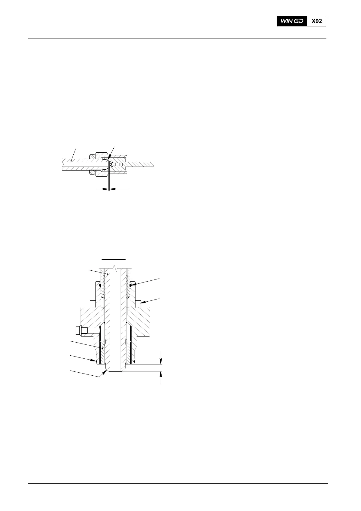
Note: If you find large notches, you must
make the HP fuel pipe (1, Fig. 13)
shorter. Make sure that there is a
minimum distance of 0.5 mm
between the countersunk screw
and the sealing face (SF) on the
HP fuel pipe.
20) Remove the screw-on sleeve (94870E,
Fig. 11) and the locknut (94870G).
21) Attach the claw (2) to the HP fuel
pipe (1).
4. Installation
1) Do a check for damage of the
O-rings (1 and 3, Fig. 14). If necessary,
replace the O-rings.
2) Remove all of the protection from the
sealing faces (SF).
3) Make sure that the claw (4) is correctly
attached to the HP fuel pipe (5).
Note: You can adjust the claw (4) with an
open-ended wrench.
4) Make sure that there is a distance of
14.0 mm between the end of the HP
fuel pipe (5) and the claw (4).
5) Make sure that the O-rings (1 and 3)
are in the correct position.
6) Apply Never-Seez NSBT to the threads
of all the screws (2).
2015
HP Fuel Pipe: Removal and Installation
Fig. 13
016.739/08
min.0.5 mm
SF
1
14.0 mm
5
Fig. 14
3
1
4
2
SF
WCH02957
IV - IV