January 2010
2-29
Phaser 7760 Color Laser Printer
004-322, 004-323
Status Indicator RAP’s
Revised
004-322 Main Motor Fail
Main Motor failure.
Troubleshooting References
Troubleshooting Procedure
004-323 Black Imaging Unit Motor Fail
Black Imaging Unit Motor has failed.
Troubleshooting References
Troubleshooting Procedure
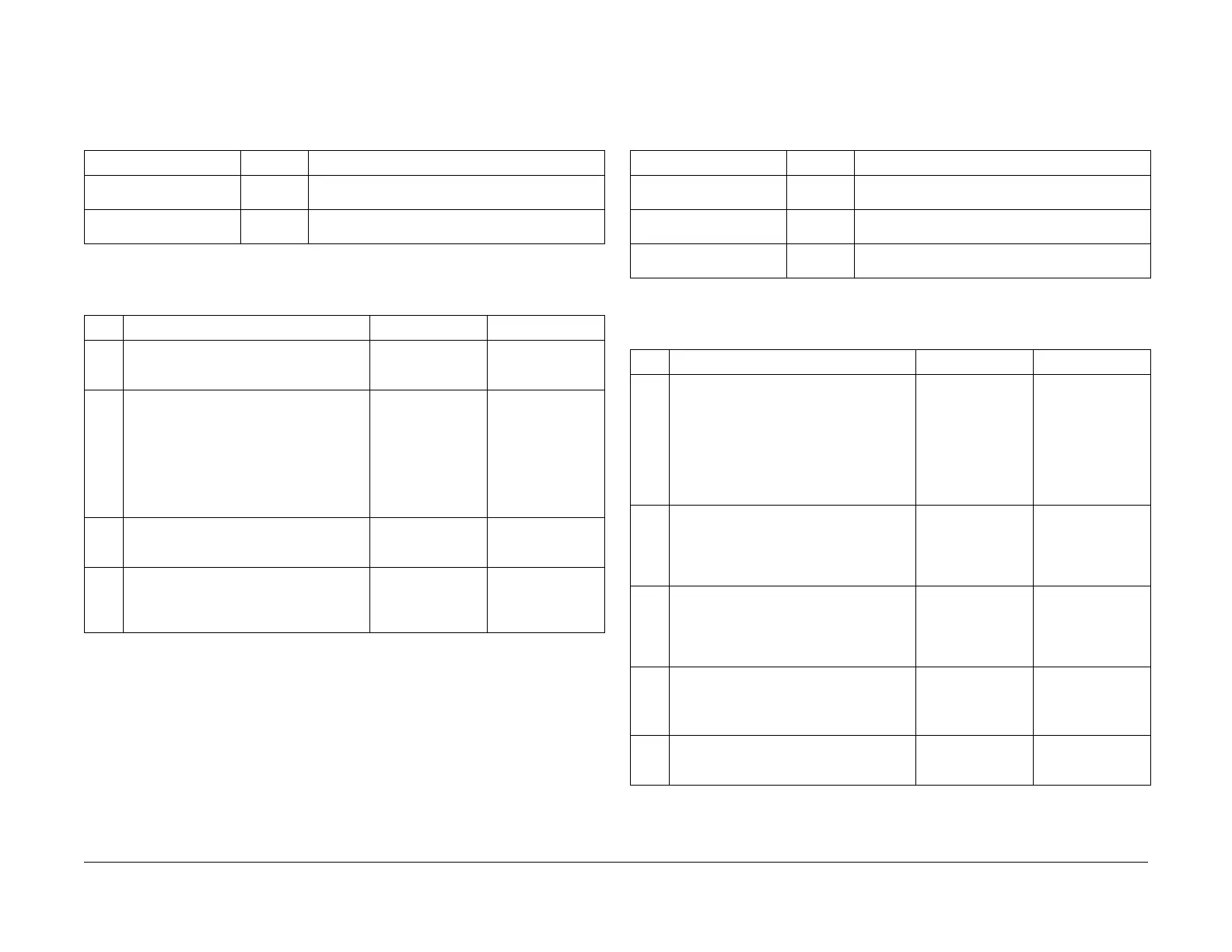
Table 1 References
Applicable Parts Parts List Wiring and Plug/Jack References
Main Drive Motor Assem-
bly
PL 1.2
I/F PWB PL 9.1 Section 7, I/F PWB, Main Motor, LVPS T11 Plug/Jack
Locations - Figure 16
Table 2 Procedure
Step Actions and Questions Yes No
1Enter Service Diagnostics Menu (refer to
Control Panel Diagnostics).
Does the Main Motor run in diagnostics?
Go to step 2. Go to step 3.
2 Does the voltage at P/J 203-8 change from
+3.3 VDC to 0 VDC when the motor is
turned on and off in Service Diagnostics?
Check the wiring
from J 203-8 to
J536-3 for open or
shorted to ground.
If the wiring is OK,
replace the Inter-
face Board (REP
1.8).
Replace the Main
Drive Motor Assem-
bly (REP 4.1).
3 Check P/J 203-1 and P/J 203-2 for +24
VDC.
Do both pins have +24 VDC?
Go to step 4. Replace the Inter-
face PWB (REP
1.8).
4 Turn off the printer and check the wiring
between J203 and J 536 for an open condi-
tion or short to ground.
Is the wiring OK?
Replace the Inter-
face PWB (REP
1.8).
Repair the wiring
harness.
Table 1 References
Applicable Parts Parts List Wiring and Plug/Jack Map References
Imaging Unit Drive Motor PL 1.1 Section 7, I/F PWB, Main Motor, LVPS T11 Plug/Jack
Locations - Figure 16
I/F PWB PL 9.1 Section 7, I/F PWB, Main Motor, LVPS T11 Plug/Jack
Locations - Figure 16
Engine Control Board
(MCU PWB)
PL 13.1 Section 7, Engine Control Board (MCU PWB) Plug/
Jack Locations - Figure 15
Table 2 Procedure
Step Actions and Questions Yes No
1 1. Enter Service Diagnostics Menu:
Printer Menu > Troubleshooting >
Service Tools > Printer Status Page
> hold the Up and Down buttons
simultaneously > Run Service Diag-
nostics > OK.
2. Select Motors/Fan Tests > OK.
Select Imaging Unit Motors > OK.
Go to step 7. Go to step 2.
2 Is the voltage at J235-4 +5 VDC? Go to step 3. Refer to Section 7,
Xerographics - Fig-
ure 2 to trouble-
shoot the missing
+5 VDC.
3 Is the voltage at J235-1 +5 VDC? Go to step 4. Refer to Section 7,
Xerographics - Fig-
ure 2 to trouble-
shoot the missing
+24 VDC.
4 1. Run the Imaging Unit Motors test
from Service Diagnostics.
2. Is the voltage at J235-5 0 VDC with
the test running?
Go to step 5. Refer to Section 7,
Xerographics - Fig-
ure 2 to trouble-
shoot.
5 Is the frequency between J235-7 between
1KHz and 1.3 KHz?
Replace the Black
Imaging Unit Motor
(REP 4.4).
Go to step 6.