January 2010
2-49
Phaser 7760 Color Laser Printer
004-363
Status Indicator RAP’s
Revised
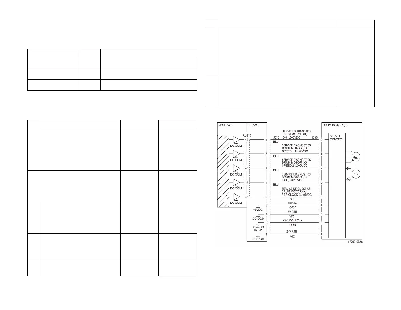
004-363 K Imaging Unit Motor Fail
Imaging Unit Motor K failure.
Troubleshooting References
Troubleshooting Procedure
Figure 1 004-363 Imaging Unit Motor K
Table 1 References
Applicable Parts Parts List Wiring and Plug/Jack References
Imaging Unit Drive Motor PL 1.1 Section 7, I/F PWB, Main Motor, LVPS T11 Plug/Jack
Locations - Figure 16
I/F PWB PL 9.1 Section 7, I/F PWB, Main Motor, LVPS T11 Plug/Jack
Locations - Figure 16
Engine Control Board
(MCU PWB)
PL 13.1 Section 7, Engine Control Board (MCU PWB) Plug/
Jack Locations - Figure 15
Table 2 Procedure
Step Actions and Questions Yes No
11.Enter Service Diagnostics Menu:
Printer Menu > Troubleshooting >
Service Tools > Printer Status Page
> hold the Up and Down buttons
simultaneously > Run Service Diag-
nostics > OK. Run the Black Imag-
ing Motor test.
2. Does the Motor operate correctly?
Go to step 7. Go to step 2.
2 Is the voltage at J535-6 +5 VDC? Go to step 3. Refer to Section 7,
BSD 8.2 Paper
Transportation) to
troubleshoot the
missing + 5 VDC -
Figure 2.
3 Is the voltage at J535-10 +24 VDC? Go to step 4. Refer to Section 7,
BSD 8.2 Paper
Transportation) to
troubleshoot the
missing + 5 VDC -
Figure 2.
4 Perform the Black Imaging Unit Motor test.
Is the voltage at J535-5 0 VDC with the test
running?
Go to step 5. Refer to Section 7,
BSD 8.2 Paper
Transportation) to
troubleshoot - Fig-
ure 2.
5 Is the frequency between J535-8 and
ground between 1 KHz and 1.3 KHz?
Replace the Black
Imaging Unit Drive
Motor (REP 4.4).
Go to step 6.
6 Is the frequency between J535-2 and
ground between 1KHz and 1.3 KHz?
Check for an open
circuit between
J534A-8 and J535-
8.
Replace in order
until resolved:
1. Engine Inter-
face Board
(REP 1.8)
2. Engine Con-
trol Board
(MCU PWB)
(REP 1.2)
7 Is +3.3 VDC present at J535-7 with the
Motor test running from Service Diagnos-
tics?
Is there is no
mechanical blind in
the Black Imaging
Unit, replace the
Black Drum Drive
Motor (REP 4.4).
Refer to Section 7, -
BSD 8.2 Paper
Transportation) to
troubleshoot the
missing +3.3 VDC -
Figure 2.
Table 2 Procedure
Step Actions and Questions Yes No