06/2014
6-4
WC 5022/5024
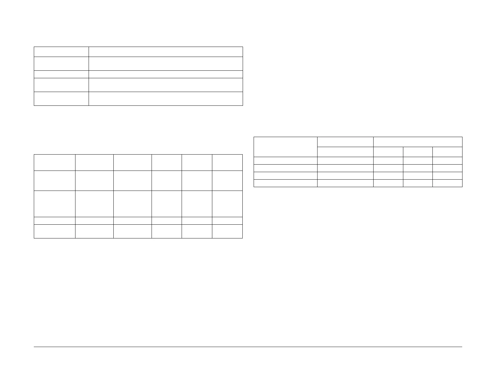
6.1.3 Operating Modes
Version 1.0
General
6.1.3 Operating Modes
The following 4 operating modes are available.
*1 Applies to the International Energy Star Program.
6.1.3.1 IOT States
The IOT systems are in the following states in each mode.
6.1.4 Machine Sizes and Basis Weights
The following are the sizes and weights of the individual products: (excluding toner)
6.1.4.1 Machine Sizes
Projecting sections such as label recesses are not included. The sizes are for when the Bypass
Tray is minimized.
The tolerance is +/-5 mm.
*1: For details on the machine sizes, refer to 6.1.4.3.
*2: This measurement is for when the Power Cord is disconnected. If it is connected, add +27
mm for Basic Models 1 and 2, and add +22 mm for Basic Model 3.
*3: The height is measured up to the top surface of the Platen Glass. Add +34 mm to this if the
Platen Cover is installed and add +119 mm if the DADF is installed.
*1: For details on the machine sizes, refer to 6.1.4.4.
*2: This measurement is for when the Power Cord is disconnected. If it is connected, add +30
mm for Basic Models 1, 2, and Full Model 1, and add +25 mm for Basic Model 3.
*3: The height is measured up to the top surface of the Platen Glass. Add +33 mm to this if the
Platen Cover is installed and add +119 mm if the DADF is installed.
6.1.4.2 Machine Weights
Measurement Conditions:
Not inclusive of Options, Output Tray, Paper, and New Toner Cartridges.
Max Floor Weight Capacity (Reference value):
= Main Unit (w/ Dup + w/ DADF) + 1TM + Stand = 36.0 kg + 10.7 kg + 19 kg = 65.7 kg
Max Floor Weight Capacity (Reference value):
= Main Unit (w/ Dup + w/ DADF) + 1TM + 2TM + Fax Kit + Margin
= 37.0 kg + 11.0 kg + 31.0 kg + 0.8 kg + 0.5 kg = 80.3 kg
6.1.4.4 Detailed Machine Sizes
1. Basic Model 1
• Machine Size (W x D x H): 595 mm x 573 mm x 580 mm (Figure 2)
Table 1
Mode State
Running Mode The data receiving/image creation/recording (printing) operation
mode
Ready Mode When the system can enter the Running Mode immediately
Low Power Mode The mode that reduces the power consumption more than the
Ready Mode
Sleep Mode *1 The mode that reduces the power consumption further more than
the Low Power Mode
Table 2
Running Mode Ready Mode
Low Power
Mode Sleep Mode Power OFF
Fusing System
(Fusing Unit)
Maintaining the
operating tem-
perature
Maintaining the
standby tem-
perature
Stop state Stop state Stop state
Recording Sys-
tem
(Transfer/Devel-
opment)
Operating state Stop state Stop state Stop state Stop state
ROS Assembly Operating state Stop state Stop state Stop state Stop state
ESS/MCU PWB
(Reference)
Operating state Standby Standby Ready to
receive
Stop state
Table 1
Product Configuration
Configuration Machine Size (mm) *1
Tray Module Width *2 Depth Height *3
Basic Model 1 None (Desktop) 595 573 580
Basic Model 2 1TM 595 573 680
Basic Model 3 1TM + Stand 595 573 1084
Full Model 1 1TM + 2TM 595 573 968
 Loading...