ELEC
SIGNALING SYSTEM
8-29
EAS00796
CHECKING THE SIGNALING SYSTEM
1. The horn fails to sound.
1. Horn switch
• Check the horn switch for continuity.
Refer to “CHECKING THE SWITCHES”.
• Is the horn switch OK?
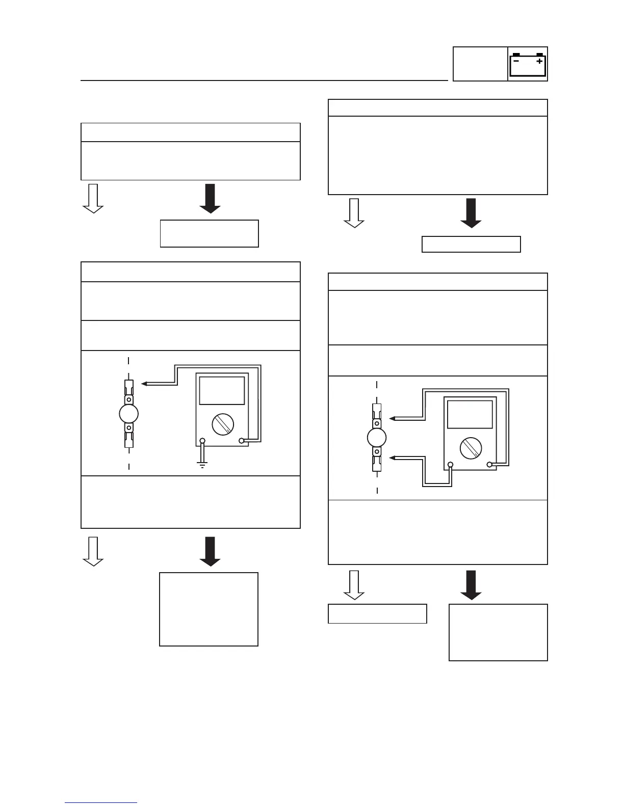
2. Voltage
• Connect the pocket tester (DC 20 V) to the
horn connector at the horn terminal as
shown.
Positive tester probe
brown
Negative tester probe
ground
• Set the main switch to “ON”.
• Measure the voltage (DC 12 V) of brown at
the horn terminal.
• Is the voltage within specification?
3. Horn
• Disconnect the pink connector at the horn
terminal.
• Connect a jumper lead to the horn terminal
and ground the jumper lead.
• Set the main switch to “ON”.
• Does the horn sound?
4. Voltage
• Disconnect the pink and brown connectors
at the horn terminal.
• Connect the pocket tester (DC 20 V) to the
horn connectors as shown.
Positive tester probe
brown
Negative tester probe
pink
• Set the main switch to “ON”. Push horn
switch
• Measure the voltage (DC 12 V) of pink at
the horn terminal.
• Is the voltage within specification?
Replace the left
handlebar switch.