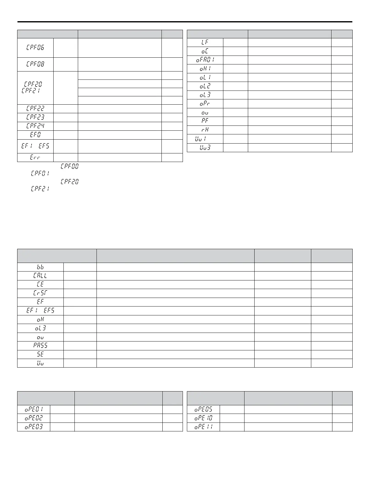
LED Operator Display Name Pg.
CPF06
Drive specification mismatch during
Terminal Board or Control Board
replacement
133
CPF08
EEPROM Serial Communications
Fault
134
or
<2>
CPF20 or
CPF21
RAM Fault 134
FLASH Memory Fault 134
Watchdog Circuit Exception 134
Clock Fault 134
CPF22 A/D Conversion Error 134
CPF23 PWM Feedback Data Fault 134
CPF24 Drive Capacity Signal Fault 134
EF0 Option Unit External Fault 134
to
EF1 to
EF5
External Fault (input terminal S1 to
S5)
134
Err EEPROM Write Error 135
LED Operator Display Name Pg.
LF Output Phase Loss 135
oC Overcurrent 135
oFA01 Option Disconnected 136
oH1 Heatsink Overheat 136
oL1 Motor Overload 136
oL2 Drive Overload 137
oL3 Overtorque Detection 1 137
oPr Operator Connection Fault 137
ov Overvoltage 142
PF Input Phase Loss 138
rH Dynamic Braking Resistor 138
<3>
Uv1 Undervoltage 139
Uv3 Soft Charge Circuit Fault 139
<1>
Displayed as when occurring at drive power up. When one of the faults occurs after successfully starting the drive, the display will show
.
<2>
Displayed as when occurring at drive power up. When one of the faults occurs after successfully starting the drive, the display will show
.
<3>
Uv1 fault is not saved to the fault history
n
Minor Faults and Alarms
When a minor fault or alarm occurs, the ALM LED flashes and the text display shows an alarm code. A fault has occurred if
the text remains lit and does not flash. Refer to Alarm Detection on page 140. An overvoltage situation, for example, can
trigger both faults and minor faults. It is therefore important to note whether the LEDs remain lit or if the LEDs flash.
Table 6.5 Minor Fault and Alarm Displays
LED Operator Display Name
Minor Fault Output
(H2-01 = 10)
Pg.
bb Drive Baseblock No output 140
CALL Serial Communication Transmission Error YES 140
CE MEMOBUS/Modbus Communication Error YES 140
CrST Cannot Reset YES 140
EF Run Command Input Error YES 141
to
EF1 to EF5 External Fault (input terminal S1 to S5) YES 141
oH Heatsink Overheat YES 141
oL3 Overtorque 1 YES 141
ov Overvoltage YES 142
PASS MEMOBUS/Modbus Test Mode Complete No output 142
SE MEMOBUS/Modbus Test Mode Fault YES 142
Uv Undervoltage YES 142
n
Operation Errors
Table 6.6
Operation Error Displays
LED Operator
Display
Name Pg.
oPE01 Drive Unit Setting Error 144
oPE02 Parameter Setting Range Error 144
oPE03 Multi-Function Input Setting Error 144
LED Operator
Display
Name Pg.
oPE05 Run Command Selection Error 144
oPE10 V/f Data Setting Error 144
oPE11 Carrier Frequency Setting Error 145
6.3 Drive Alarms, Faults, and Errors
132
YASKAWA ELECTRIC SIEP C710606 31B YASKAWA AC Drive – J1000 Technical Manual
http://nicontrols.com
 Loading...


