5 Mounting and Wiring
5.2.1 Connectors
5-8
5.2 MP2100/MP2100M Connections
5.2.1 Connectors
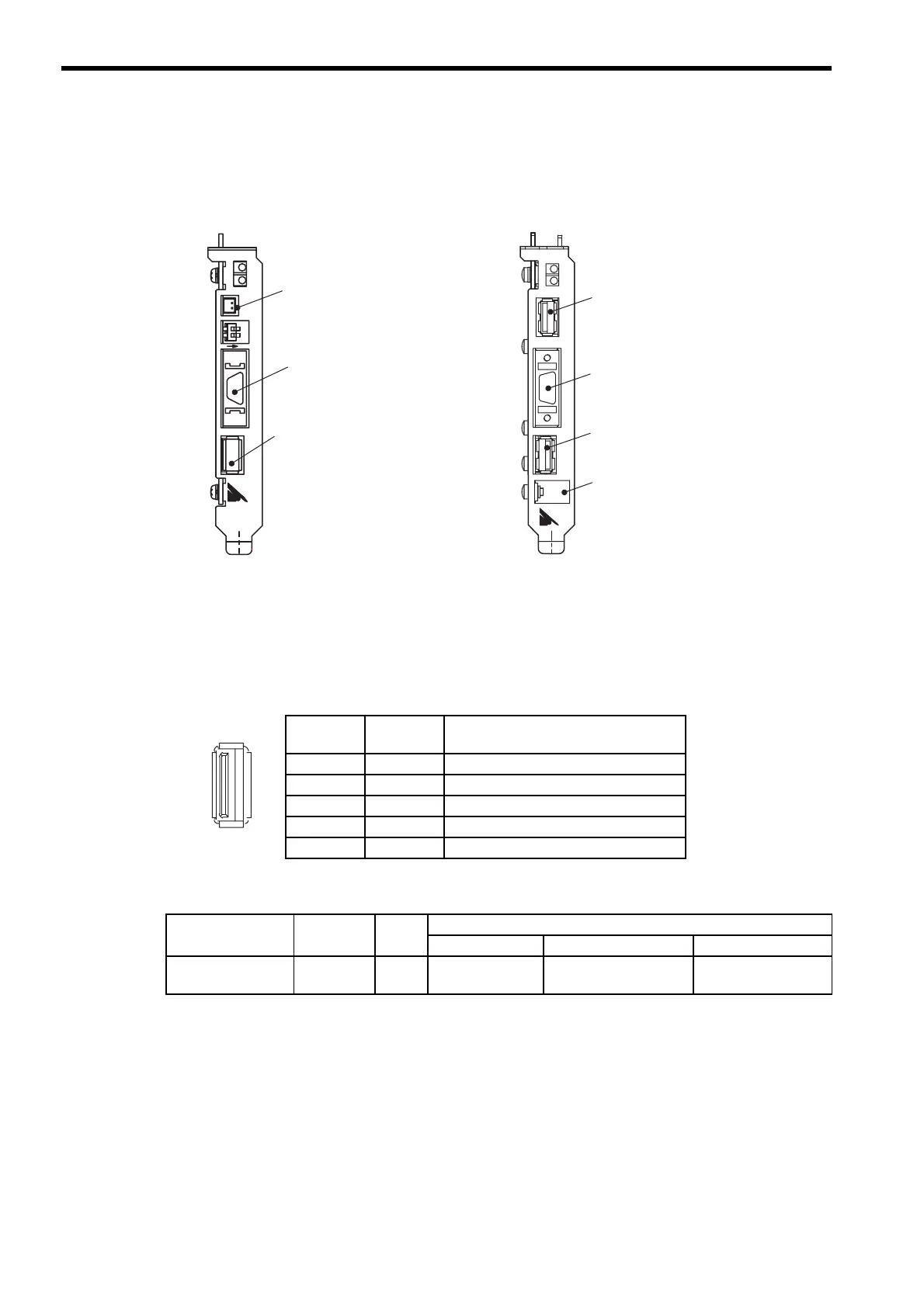
The following diagram shows the connectors for the MP2100/MP2100M.
5.2.2 MECHATROLINK-
I
/
II
Connection
(1) MECHATROLINK-
I
/
II
Connector (M-I / II)
MECHATROLINK-I/II connector is used to connect the MP2100/MP2100M and the SERVOPACKs and distrib-
uted I/O Module.
(2) Connector Specifications
ON
I/O
BAT
12
MP2100
BAT
TX
S2
S1
YASKAWA
M-I/II
MECHATROLINK
connector
I/O connector
Battery connector
MP2100
BAT
TX
PORT2
M-I/II
S1
S2
MP2100M
I/OBAT
YASKAWA
PORT1
M-I/II
Battery hole
I/O connector
SVB Module
MECHATROLINK connector
CPU Module
MECHATROLINK connector
MP2100M
Pin
Number
Signal
Name
Description
1 (NC) Not used.
2/DATASignal
−
side
3DATA Signal + side
4SH Not used.
Shell Shield Connects the shield wire.
Name
Connector
Name
No. of
Pins
Connector Model
Module Cable Manufacturer
MECHATROLINK
Connector
M-I/II
4
USB-AR41-T11 DUSB-APA41B1-C50 Daiichi Denshi Kogyo
K.K.
 Loading...


