2 System Configuration
2.1.1 MP2100 Basic System Configuration
2-2
2.1 MP2100 System Configuration
2.1.1 MP2100 Basic System Configuration
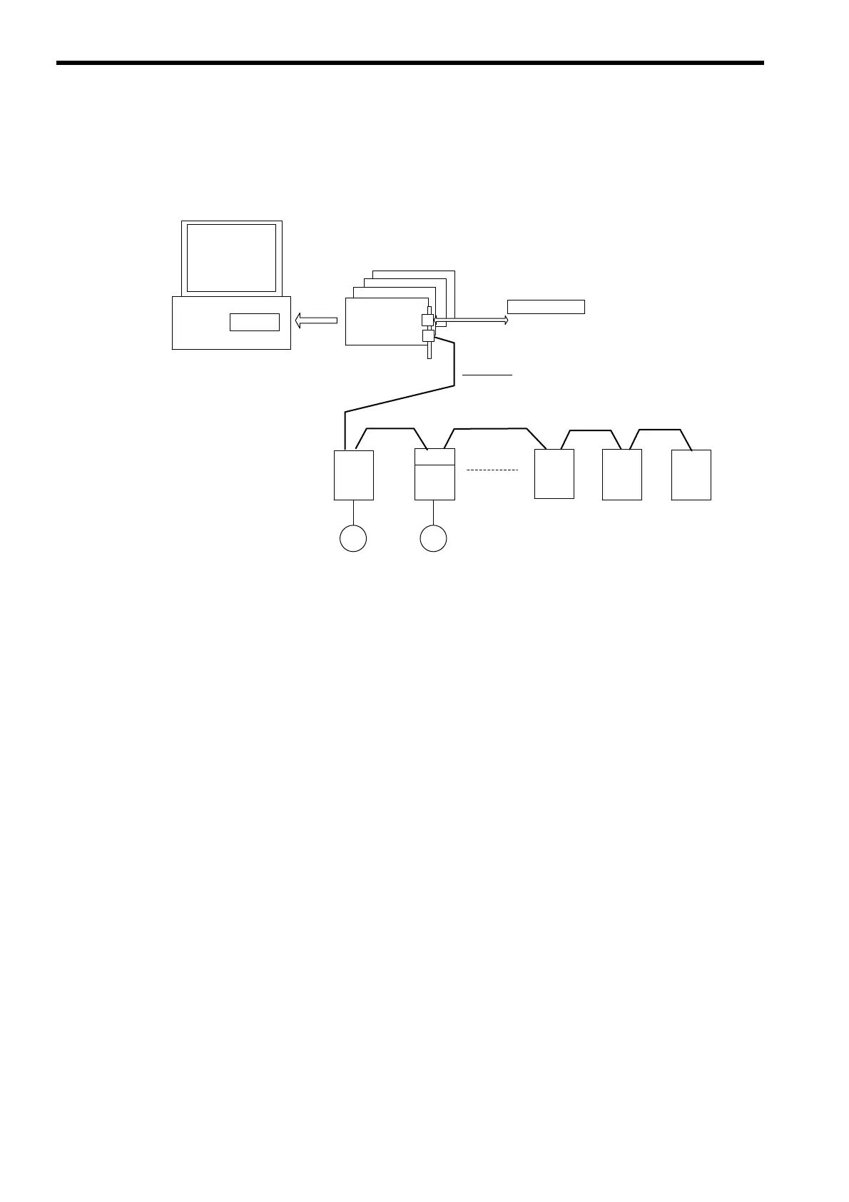
The following diagram shows the basic system configuration for the MP2100.
Note 1. Up to 21 devices can be connected to MECHATROLINK-
II. (The SERVOPACKs and
Inverters can be connected for to up to 16 axes.)
2. Up to 9 digital I/O points (5 inputs and 4 outputs) can be used.
2.1.2 Precautions
The following precautions must be followed when designing a system using the MP2100.
• Use the connecting cables and connectors recommended by Yaskawa.
Yaskawa has a range of cables. Always check the device to be used and select the correct cable for the
device.
• Different SERVOPACKs are connected to MECHATROLINK-I and MECHATROLINK-
II.
Refer to the list and select the appropriate SERVOPACKs.
• If devices compatible with MECHATROLINK-I (4 Mbps) and with MECHATROLINK-
II (
10 Mbps) are
used together, make the all settings for MECHATROLINK-I (4 Mbps).
• When connecting SERVOPACKs via MECHATROLINK, connect the overtravel, zero point return decel-
eration limit switch and external latch signals to the SERVOPACKs.
SGDS
M
IO2310
MECHATROLINK-II
Input: 5 points
Output: 4 points
(Interrupt input, etc.)
External I/O
Host computer
MPE720
Motion API
MP2100
Max.4 boards
SGDH
NS115
M
PL2900
PL2910
Max.5 I/O stations
Max.16
Servo or
Inverter axes
 Loading...


