EasyManua.ls Logo

YASKAWA MP2100 Series User Manual

YASKAWA MP2100 Series
455 pages
To Next Page IconTo Next Page
To Previous Page IconTo Previous Page
Page #242 background imageLoading...
Page #242 background image
8.5 Interpolation (INTERPOLATE)
8-33
8
8.5 Interpolation (INTERPOLATE)
The INTERPOLATE command positions the axis according to the target position that changes in sync with the
high-speed scan. The positioning data is generated by a ladder program.
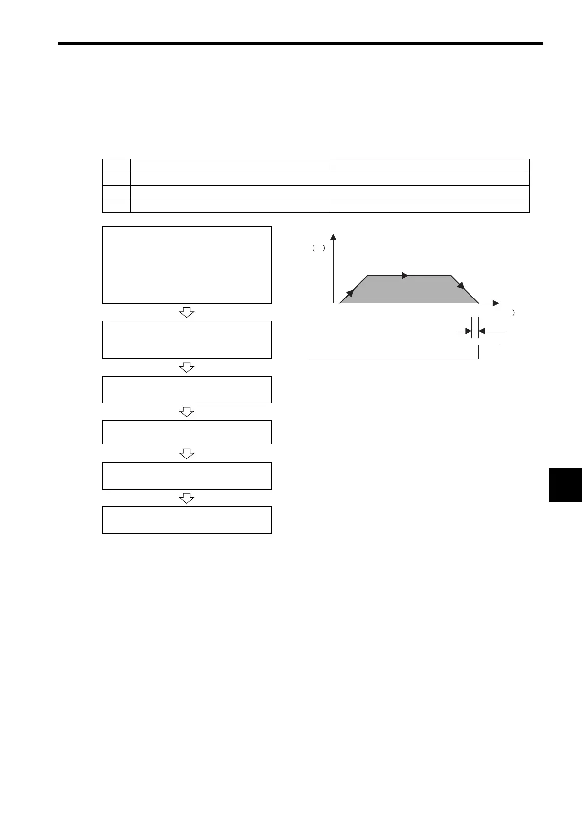
(1) Operating Procedure
(2) Holding and Aborting
The axis will decelerate to a stop if there is no change in the target position each high-speed scan.
The Command Pause bit (OB

090) and the Command Abort bit (OB

091) cannot be used.
No. Execution Conditions Confirmation Method
1 There are no alarms. Both IL

02 and IL

04 are 0.
2 The Servo ON condition. IB

001 is ON.
3 Motion command execution has been completed. IW

08 is 0 and IB

090 is OFF.
Set the motion setting parameters.
• Target Position: OL

1C
• Acceleration/Deceleration Filter Type:
OW

03
• Speed Loop P/PI Switch: OW

01
• Speed Feed Forward: OW

30
• Speed feed forward can be applied.
• Generate the positioning data each high-speed scan from the
ladder logic program.
• The travel speed is calculated automatically.
• The Command Pause (OB

090) cannot be used.
• The Command Abort (OB

091) cannot be used.
• Change a motion command to stop interpolation execution.
Execute the interpolation (INTERPOLATE)
motion command.
• Set OW

08 to 4.
Positioning starts.
• IW

08 will be 4 during positioning.
Change the Target Position (OL

1C)
every high-speed scan.
Positioning Completed
• IB

0C1 will turn ON.
Execute NOP motion command.
• Set OW

08 to 0.
Position
Speed
%
Time (t
0
Positioning Completed Width
POSCOMP

Table of Contents

Question and Answer IconNeed help?

Do you have a question about the YASKAWA MP2100 Series and is the answer not in the manual?

YASKAWA MP2100 Series Specifications

General IconGeneral
BrandYASKAWA
ModelMP2100 Series
CategoryController
LanguageEnglish

Summary

Safety Information

Safety Precautions

Essential precautions for handling, installation, operation, and maintenance of the MP2100/MP2100M.

Mounting and Wiring

Recommended Computer Specifications

Specifies hardware and software requirements for the host computer used with the MP2100/MP2100M.

Installing the Drivers

Step-by-step guide to install necessary drivers for the MP2100/MP2100M on the host computer.

Verifying Driver Installation

Procedure to confirm proper recognition and driver installation of the MP2100/MP2100M.

Basic System Operation

Operating Modes

Explains the different operating modes like Online and Offline.

MP2100 Mode Switch Settings

Details the functions of mode switches for controlling MP2100 startup sequences.

Startup Sequence

Provides a flowchart detailing the system startup process for the MP2100/MP2100M.

Registers

Register Designation Methods

Explains direct register number and symbolic designation methods for addressing registers.

Self-configuration

MECHATROLINK Station Information

Describes the process of automatically identifying MECHATROLINK devices connected to the system.

Motion API

Installing MP2100/MP2100M

Step-by-step instructions for installing the Motion API software package on the host computer.

Specifications

Hardware Specifications

Details the physical and electrical specifications of the MP2100/MP2100M hardware.

Motion Parameter Details

Lists and describes various motion parameters used for controlling axis movement.

Acceleration/Deceleration Settings

Explains how to set acceleration and deceleration rates or time constants.

Motion Commands

Command Table

Lists available motion commands with their codes, names, and descriptions.

Positioning (POSING)

Details the POSING command for axis positioning with specified speed and acceleration/deceleration.

External Positioning (EX_POSING)

Explains the EX_POSING command for positioning an axis based on external signals.

Zero Point Return (ZRET)

Describes the ZRET command for returning an axis to its zero point.

JOG Operation (FEED)

Details the FEED command for manual axis movement.

STEP Operation (STEP)

Explains the STEP command for positioning with specified travel distance.

Zero Point Setting (ZSET)

Describes the ZSET command to set the current position as the machine coordinate system's zero point.

Control Block Diagrams

Position Control

Illustrates the control block diagram for position control operations within the MP2100/MP2100M.

Absolute Position Detection

Structure of the Absolute Position Detection Function

Provides an overview of the absolute position detection function and its features.

Startup the Absolute Position Detection Function

Step-by-step guide to start the absolute position detection system.

Using an Absolute Encoder

Explains precautions and zero point setting for finite length axes with absolute encoders.

SVR Virtual Motion Module

Overview

Provides an overview of the SVR Virtual Motion Module and its system configuration.

Motion Parameters

Lists motion parameters used by the SVR and their default values.

Maintenance and Inspection

Inspection Items

Lists daily and regular inspection items that must be performed by the customer.

Troubleshooting

Overview of Troubleshooting

Outlines methods for checking system issues: symptoms, error codes, and monitor functions.

System Errors

Explains system error details and remedies.

Motion Program Alarms

Lists and describes motion program alarm codes and their remedies.

Application Precautions

Overtravel Function

Explains how to use the overtravel function and its parameter settings.

Software Limit Function

Explains the soft limit function for machine movement range monitoring.

Appendix A Motion API

Motion API

Lists the common, sequential, and system APIs for motion control.

Appendix B Parameters That are Automatically Updated

Parameters Updated when a Connection is Established

Details parameters updated automatically when a connection is established between MP2100/MP2100M and SERVOPACK.

Appendix C List of System Registers

System Service Registers

Lists system registers common to all drawings, specific to high-speed, and low-speed scan drawings.

Related product manuals