13.2 System Errors
13-7
13
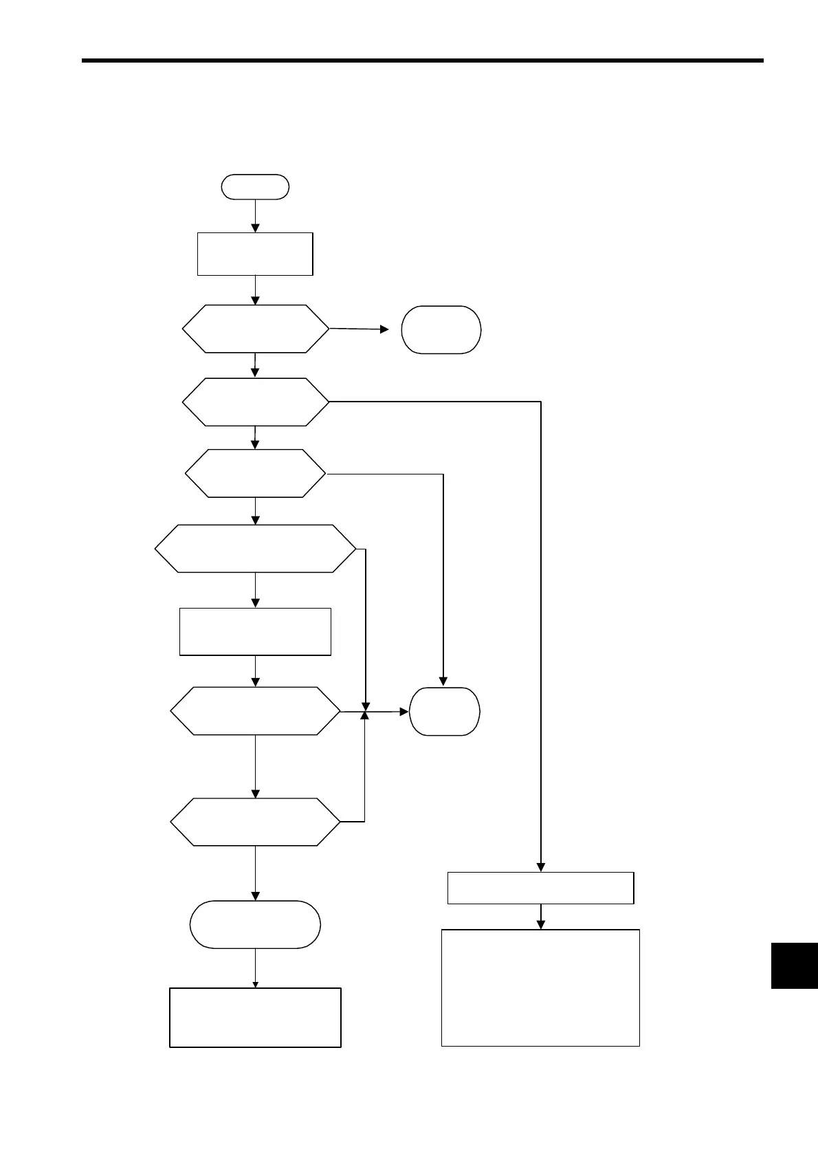
13.2.2 Processing Flow When a System Error Occurs
The following illustration shows the processing flow when a system error occurs.
* 1. See Indicator Details in 13.1.3 Indicator Errors for more details on indicator patterns.
* 2. With MP2100M, STOP is set by turning ON pin 6 of mode switch 1.
START
(1)
(2)
NO
YES
NO
NO
YES
YES
YES
NO
YES
YES
NO
Classify error contents
based on the indicator
pattern.*
1
Battery alarm?
(BAT indicator lit?)
Replace
battery
Warning
Classification = Warning?
(S2 indicator lit (red) or
blinking (red)?)
Classification =
Fatal error? (S1 indicator
blinking (red)?)
Fatal error
Hardware failure/watchdog time error?
(Only S1 indicator light (red)?)
Online Stop Mode
Only S1 indicator lights (green)?
Hardware
failure
User program
error
Check the contents of
SW00050. Watchdog
timeout error?
User program error
NO
Check the contents of CPU error
status (SW00041).
See
13.2.3
Processing Flow for a
Ladder Program Error
and check
the location where the error oc-
curred.
(1)Operation error (SB000418)
See
Ladder Program User Operation
Error Status
in 13.2.4
System Regis-
ter Configuration
.
(2)I/O error (SB000419)
See
System I/O Error Status in 13.2.4
System Register Configuration
.
Turn OFF pin 2 of the Mode
Switch 1 (STOP) and turn
power OFF and ON.*
2
 Loading...


