6 Basic System Operation
6.3.1 Drawings (DWGs)
6-8
6.3 User Programs
This section explains the basic operation of the user program. The MP2100/MP2100M’s user programs include
ladder program and motion program. For details, refer to the following manuals.
• Machine Controller MP900 Series User’s Manual Ladder Programming
(Manual No.: SIEZ-C887-1.2)
• Machine Controller MP
User’s Manual Motion Programming
(Manual No.: SIEZ-C887-1.3)
• Machine Controller MP900 Series New Ladder Editor Programming Manual
(Manual No.: SIE-C887-13.1)
• Machine Controller MP900 Series New Ladder Editor User’s Manual
(Manual No.: SIE-C887-13.2)
6.3.1 Drawings (DWGs)
User programs are managed in units of programming called drawings. Each drawing is identified by a drawing
number (DWG No.). These drawings serve as the basis of user programs.
The drawings include parent drawings, child drawings, grandchild drawings, and operation error drawings.
Besides the drawings, there are functions that can be freely called from each drawing.
• Parent Drawings
Parent drawings are executed automatically by the system program when the execution condition is
established. See the following table for execution conditions.
• Child Drawings
Child drawings are executed by being called from a parent drawing using the SEE instruction.
• Grandchild Drawings
Grandchild drawings are executed by being called from a child drawing using the SEE instruction.
• Operation Error Drawings
Operation error drawings are executed automatically by the system program when an operation error
occurs.
• Functions
Functions are executed by being called from a parent, child, or grandchild drawing using the FSTART
instruction.
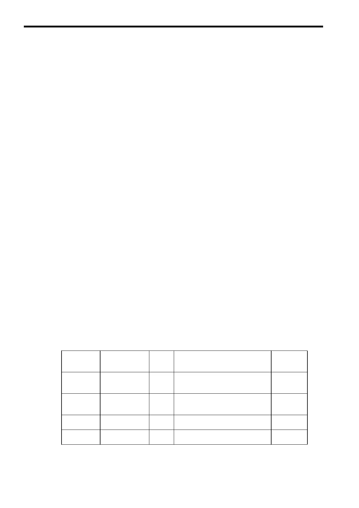
• Types and Priority Levels of Drawings
Drawings are classified by the first character of the drawing number (A, I, H, L) according to the purpose of
the process. The priority levels and execution conditions are as shown in the following table.
Type of
Parent
Drawing
Role of Drawing
Priority
Level
Execution Condition
Number of
Drawings
DWG.A
(drawing A)
Startup process
1
Started when power is turned ON (exe-
cuted once only when the power is turned
ON).
64
DWG.I
(drawing I)
Interrupt process
2
Executed by external interrupts, such as
Optional Module DI interrupts or counter
interrupts.
64
DWG.H
(drawing H)
High-speed scan
process
3
Started at a fixed interval (executed during
each high-speed scan).
200
DWG.L
(drawing L)
Low-speed scan
process
4
Started at a fixed interval (executed during
each low-speed scan).
500
 Loading...


