14.1 Controlling a Vertical Axis
14-3
14
14.1.2 Connections to SGDH-
E or SGDS-
1
SERVOPACK
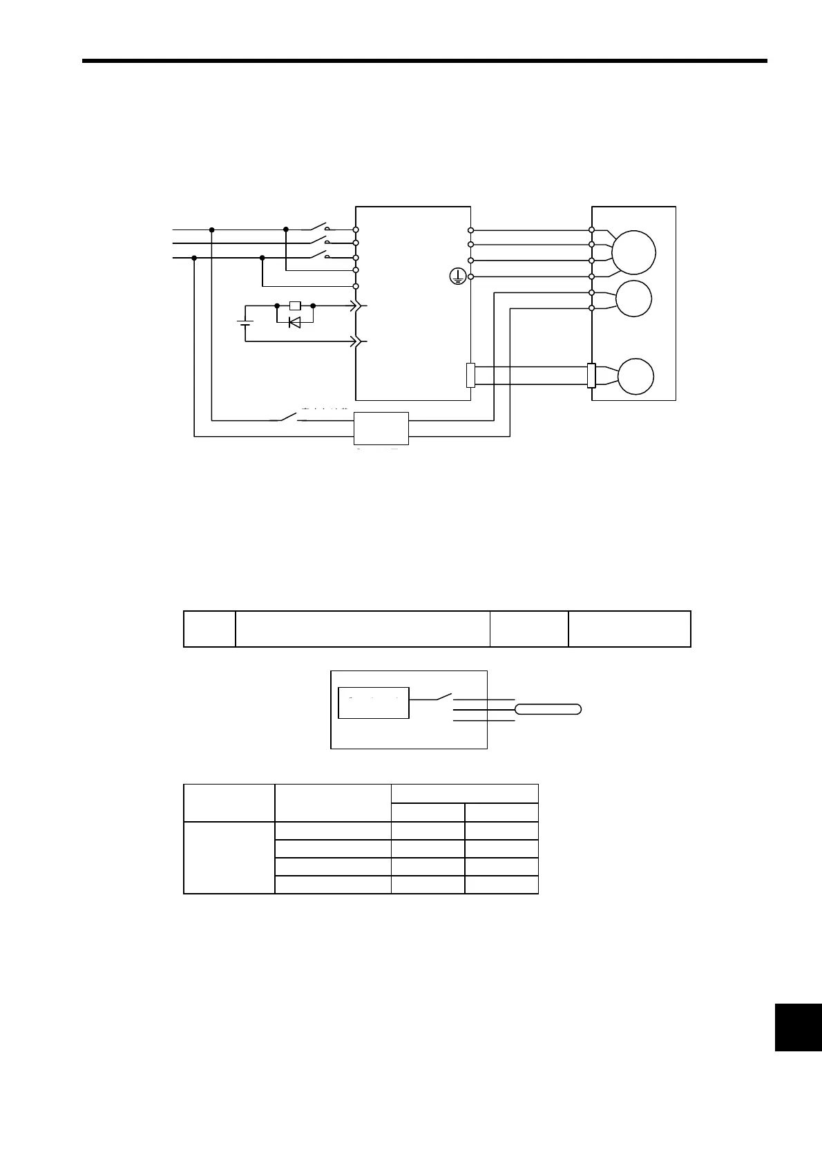
(1) Connection Example
* 1. The output terminal allocated using parameter Pn50F.2.
* 2. Brake control relay
* 3. There are 200-V and 100-V brake power supplies.
(2) Parameter Settings
(a) Pn-50F.2 (Output Signal Selection 2)
The following parameter determines which pin of CN1 will be used to output the BK signal.
Select which terminal is used to output /BK. (Here, 2 is set.)
M
BK
PG
ブレーキ付き
サーボモータ
U
V
W
CN2
赤
黒
青または黄
白
AC DC
BK-RY
+24V
L1
L2
L3
L1C
L2C
ブレーキ電源
SGDH
または
SGDS
サーボパック
電源
27-
28-
/BK+
/BK-
*2
*3
A(1)
B(2)
C(3)
D(4)
E(5)
F(6)
BK-RY
*1
*1
Blue or yellow
Red
White
Black
Power
supply
SGDH or SGDS
SERVOPACK
Brake power supply*
3
Servomotor
with brake
Pn50F
Output Signal Selection 2
Default
0
Speed, torque, or
position control
Parameter Setting
Output Terminal (
CN1
)
12
Pn50F.2
0
--
12526
22728
32930
/BK
ブレーキインタ
ロック出力
Pn50F.2
1
2
3
入力端子
CN1-25,26(SO1)
CN1-27,28(SO2)
CN1-29,30(SO3)
Brake interlock
outputs
Output
terminals
 Loading...


