5 Mounting and Wiring
5.2.3 I/O Connection
5-12
5.2.3 I/O Connection
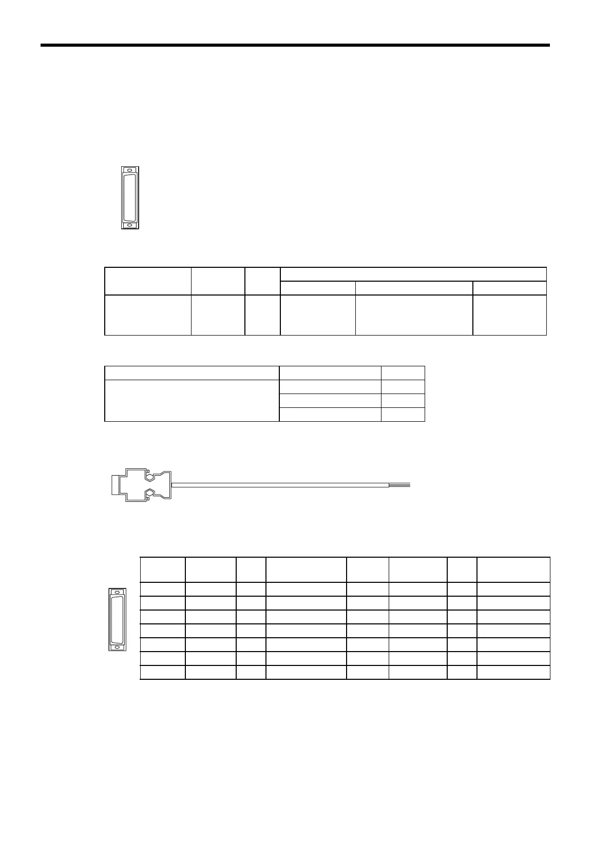
(1) I/O Connector
I/O connector is used to connect the MP2100/MP2100M and external I/O signals.
External input: 5 points; External output: 4 points
(2) Connector Specifications
(3) Cables
(4) External Appearance of I/O Cable
JEPMC-W2062-
(5) Connector Pin Arrangement
The following table shows the connector pin arrangement.
Note: P: Power input; I: Input signal; O: Open-collector output
Name
Connector
Name
No. of
Pins
Connector Model
Module Cable Manufacturer
I/O Connector I/O
14
10214-52A2JL
• 10114-3000VE Connector
• 10314-52A0-008 or
10314-52F0-008 shell
Sumitomo 3M
Limited.
Name Model Number Length
I/O Cable (loose wires
)
JEPMC-W2062-A5
0.5 m
JEPMC-W2062-01
1 m
JEPMC-W2062-03
3 m
Pin
Number
Signal
Name
I/O Remarks
Pin
Number
Signal
Name
I/O Remarks
1 DI_24 V
P
Input common 8 DI_24V
P
Input common
2DI_00
I
Input 00 9 DI_02
I
Input 02
3DI_01
I
Input 01 10 DI_03
I
Input 03
4DI_04
I
Input 04 11 DO_24V
P
+24V input
5DO_COM
P
Output common 12 DO_COM
P
Output common
6DO_00
O
Output 00 13 DO_02
O
Output 02
7DO_01
O
Output 01 14 DO_03
O
Output 03
 Loading...


