5.2 MP2100/MP2100M Connections
5-13
5
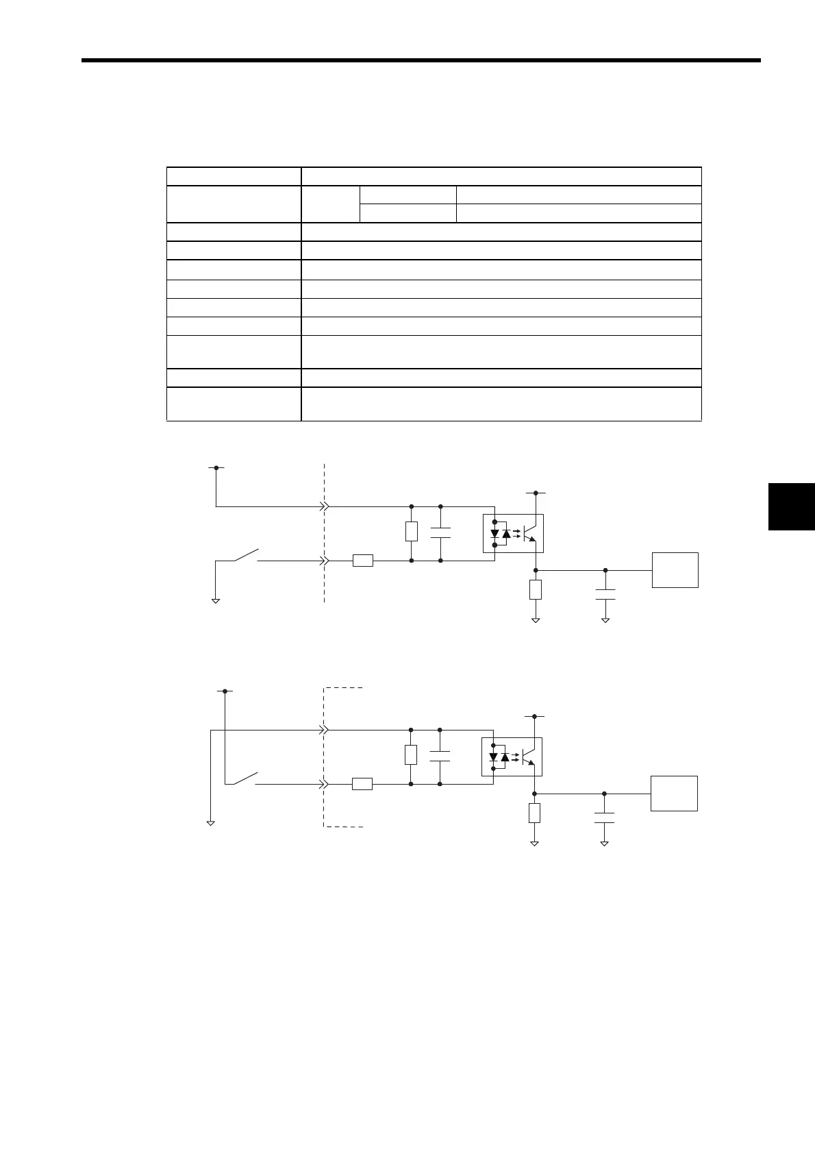
(6) Input Circuits
The following table shows the I/O Connector input circuit specifications.
Figure 5.1 Digital Input Circuit (Sink mode Input)
Figure 5.2 Digital Input Circuit (Source mode Input)
Item Specifications
Inputs 5 points DI-00 General-purpose input (shared with interrupts)
DI-01 to DI-04 General-purpose input
Input Format Sink mode/source mode input
Isolation Method Photocoupler
Input Voltage
±
24 VDC,
±
20
%
Input Current 4.1 mA (typ.)
ON Voltage/Current 15 VDC min./2.0 mA min.
OFF Voltage/Current 5 VDC max./1.0 mA max.
ON Time/OFF Time ON: 1 ms max.
OFF: 1 ms max.
Number of Commons 5 points
Other Functions DI-00 is shared with an interrupt input. If DI-00 is turned ON while interrupts
are enabled, the interrupt processing drawing is executed.
0.01µF
+5 V
680 Ω
22 kΩ
0.01µF
Input
register
DI_COM
DI_IN
+24 V
5.6 kΩ/0.5 W
0
24
+5 V
680 Ω
22 kΩ
0.01µF
Input
register
DI_COM
DI_IN
+24 V
0
24
0.01µF
5.6 kΩ/0.5 W
 Loading...


