5.2 MP2100/MP2100M Connections
5-15
5
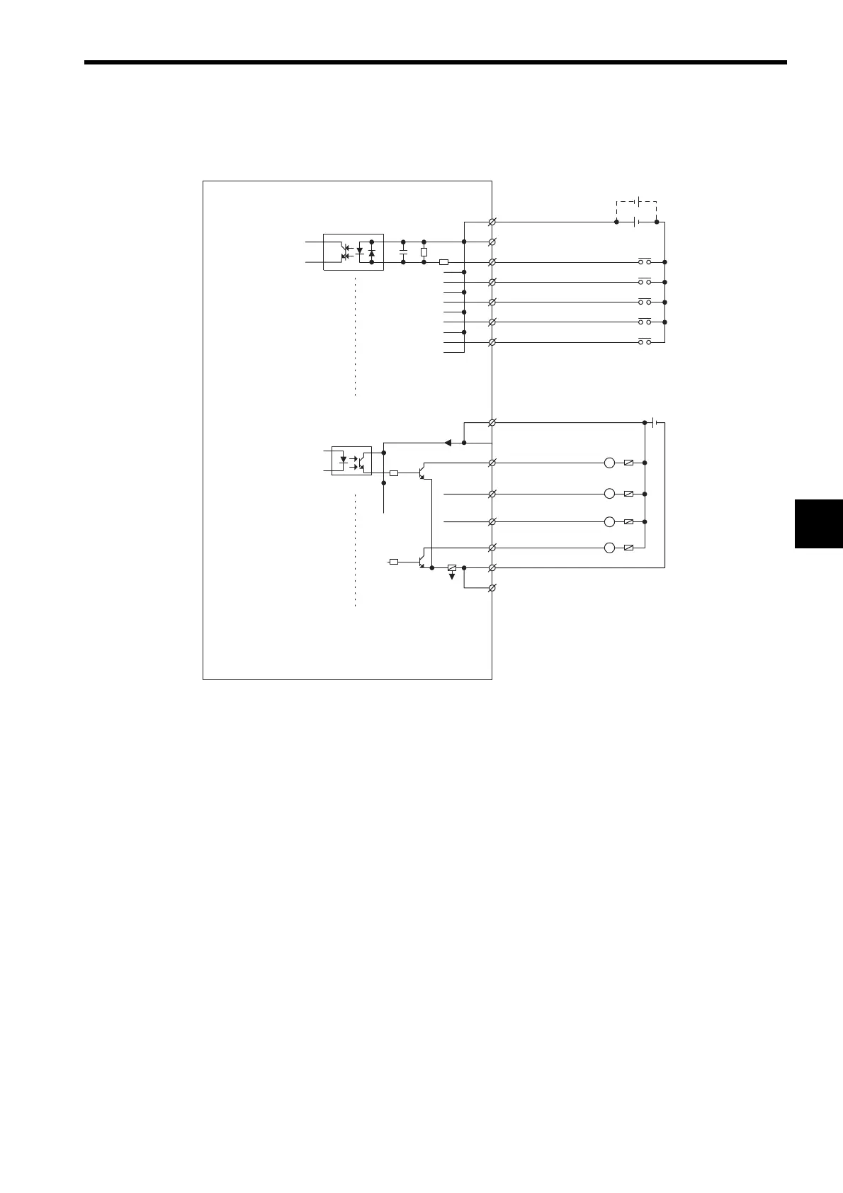
(8) I/O Connector Connections
The following diagram shows the connections for the I/O connector.
Note: Connect a fuse suitable for the load specifications in the output signal circuit in series with the load.
If an external fuse is not connected, load shorts or overloads may result in fire, destruction of the
load device, or damage to the output element.
Fuse
Digital input
Digital output
External
input
signals
24 VDC
24 VDC
External
ouput
signals
8
L
L
L
L
DC24V (DI)
DI_00
DI_01
DI_02
DI_03
DI_04
DC24V (DO)
DO_00
DO_01
DO_02
DO_03
DO_COM
DO_COM
2
3
9
10
4
1
11
6
7
13
14
5
12
DI_COM
Fuse
 Loading...


