7.2 Motion Parameter Details
7-19
7
(18) Positioning Completed Width 2
(19) Deviation Abnormal Detection Value
OL
20
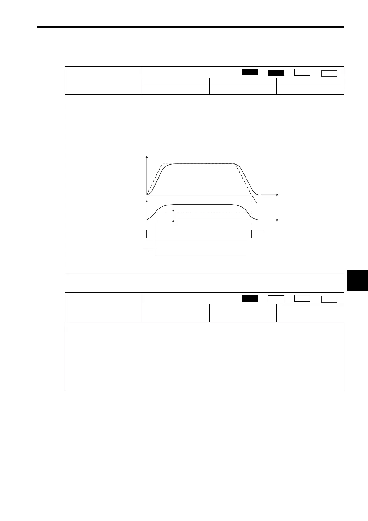
Positioning Completed Width 2
Setting Range Setting Unit Default Value
0 to 65535
Reference unit
0
The Position Proximity (IB
0C3) will be turned ON when the absolute value of the difference between the command
position and the feedback position is less than the value set here.
If the Positioning Completed Width 2 is set to 0, the Position Proximity bit (monitoring parameter IB
0C3) will be
turned ON when the reference pulses have been distributed. (monitoring parameter IB
0C0)
If the Positioning Completed Width 2 is set to a value other than 0, this bit will be turned ON when the result of subtracting
the Machine Coordinate Feedback Position (monitoring parameter IL
16) from the Machine Coordinate System Posi-
tion (monitoring parameter IL
12) is less than the Position Completed Width 2, even if the reference pulses have not
been distributed. This parameter has no relation to the SERVOPACK parameter Position Proximity (NEAR) Signal Width.
■
Related Parameters
IB
0C3: Position Proximity
OL
22
Deviation Abnormal Detection Value
Setting Range Setting Unit Default Value
0 to 2
31
−
1
Reference unit
2
31
−
1
Set the value to detect an excessively following error during position control.
The Excessively Following Error bit (IB
049) will turn ON if the result from subtracting the Machine Coordinate Feed-
back Position (monitoring parameter IL
16) from the Machine Coordinate System Position (monitoring parameter
IL
12) exceeds the value set here. An excessive following error will not be detected if this value is set to 0.
■
Related Parameters
An excessively following error can be set to be treated either as a warning or as an alarm in the Deviation Abnormal
Detection Error Level in Mode 1 (setting parameter OB
010).
OB
010 = OFF: Warning (continues axis operation)
OB
010 = ON: Alarm (stops axis operation)
Position
Phase
Speed
Torque
Speed
Position Error
Positioning Completed Width 2
Distribution completed
Positioning Completed
Width 2 = 0
Positioning Completed
Width 2 ≠ 0
Position
Phase
Speed
Torque
 Loading...


