9 Control Block Diagrams
9.1.2 Phase Control
9-8
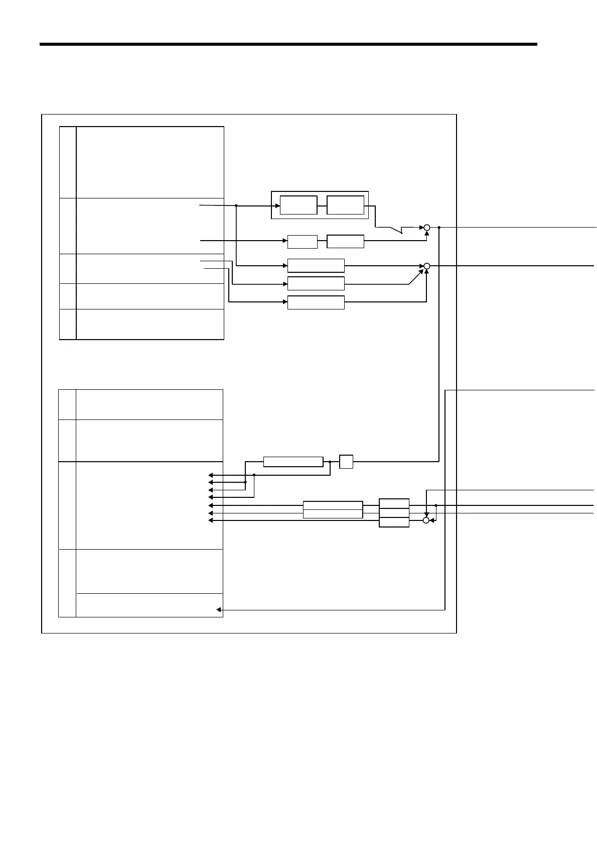
(2) Control Block Diagram for Phase Control
MP2100/MP2100M
SVB
OW00 Run Commands
OW03
Function 1
OW05 Function 3
OW08 Motion Command
OW09 Motion Command Options
OW0A Motion Subcommand
OL10 Speed Reference
OL1E Positioning Completed Width
OL20 Positioning Completed Width 2
OL22 Deviation Abnormal Detection Value
OW26 Position Complete Timeout
OL28 Phase Compensation
OW31 Speed Amends
OL16
Secondly Speed Compensation
OW3A
S-Curve Acceleration Time
OL48 Zero Point Offset
OL4A Work Coordinate System Offset
OL4C Preset Data of POSMAX Turn
IW00 Drive Status
IL02 Warning
IL04 Alarm
IW08 Servo Command Type Response
IW09 Servo Module Command Status
IW0A
Motion Subcommand Response Code
IW0B Motion Subcommand Status
IW0C Position Management Status
IL0E
Machine Coordinate Target Position (TPOS)
IL10 Target Position (CPOS)
IL12
Machine Coordinate System Position (MPOS)
IL14 32-bit Coordinate System Position (DPOS)
IL16 Machine Coordinate Feedback Position (APOS)
IL18 Machine Coordinate Latch Position (LPOS)
IL1A Position Error (PERR)
IL1C Target Position Difference Monitor
IL1E POSMAX Number of Turns
IL20 Speed Reference Output Monitor
IW2C Network Servo Status
IW2D Servo Alarm Code
IW2E Network Servo I/O Monitor
IW2F
Network Servo User Monitor Information
IW30 Servo User Monitor 2
IL40 Feedback Speed
IL42 Torque (Thrust) Reference Monitor
Run Settings
Run
Information
Position InformationSERVOPACK Information
Motion Command
Information
Time
constants
Gain
Coordinates
Speed/Position
References
Σ
POSMAX processing
−
+
PHREF
OFF
Move command generation processing
+
+
+
+
+
Target position
difference
operation
Target
position
operation
Difference
operation
Electronic
gear
Speed reference
unit change
Speed reference
unit change
Speed reference
unit change
POSMAX processing
POSMAX processing
Electronic
gear
Electronic
gear
Electronic
gear
 Loading...


