Setting 63: Field Weakening
Enabled in V/f Control. When this input is closed, Field Weakening is performed. For details, see d6: Field Weakening and
Field Forcing.
Setting 65, 66: KEB Ride-Thru 1 (N.C.), 2 (N.O.)
Enables the KEB Ride-Thru function selected in parameter L2-29. Refer to KEB Ride-Thru Function on page 241 for more
information on this function.
Digital Input Function
Drive Operation
Input Open Input Closed
Setting 65 (N.C.) KEB Ride-Thru Deceleration Normal operation
Setting 66 (N.O.) Normal operation KEB Ride-Thru Deceleration
Note: Simultaneously assigning KEB Ride-Thru 1 and KEB Ride-Thru 2 to the input terminals will trigger an oPE03 error.
Setting 67: Communication Test Mode
The drive has a built-in function to self-diagnose serial communications operation. The test involves wiring the send and
receive terminals of the RS-422/RS-485 port together. The drive transmits data and then confirms that the communications
are received normally. Refer to Self-Diagnostics on page 538 for details on how to use this function.
Setting 68: High Slip Braking (HSB)
Closing an input programmed for this function triggers High Slip Braking. After starting HSB, bring the drive to a complete
stop and remove the HSB command before restarting. Refer to n3: High Slip Braking (HSB) and Overexcitation Braking
on page 264.
Setting 6A: Drive Enable
A digital input configured as a “Drive enable” (H1-oo = 6A) will prevent the drive from executing a Run command until
the input is closed. When the input is open, the digital operator will display “dnE” to indicate that the drive is disabled.
If a Run command is enabled before the terminal set for “Drive enable” closes, then the drive will not run until the Run
command is cycled (i.e., a new Run command is required). If the input is opened while the drive is running, the drive will stop
according to the stop method set to b1-03 (Refer to b1-03: Stopping Method Selection on page 149).
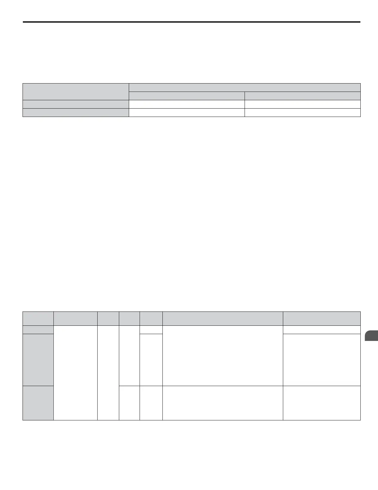
Setting 75, 76: Up 2/Down 2 Function
The Up/Down 2 function adds a bias to the frequency reference. The input programmed for 75 will increase the bias and the
input programmed for 76 will decrease the bias. Table 5.32 explains how the Up/Down 2 function works depending on the
frequency reference source and parameters d4-01, d5-03, and d4-05. Refer to d4: Frequency Reference Hold and Up/Down
2 Function on page 186 for detailed explanations of these and other Up/Down 2 related parameters.
Note: 1. The Up/Down 2 functions must be set as a pair.
2. When using the Up/Down 2 function, set appropriate bias limit values to parameters d4-08 and d4-09.
Table 5.32 Up/Down 2 Operations
Condition
Freq. Ref.
Source
d4-03 d4-05 d4-01 Operation Frequency Saved
1
Multi-Step Speed
Reference
0
0
0 • Accelerates (increases the bias) while the Up 2
terminal is closed.
• Decelerates (decreases the bias) while Down 2 is
closed.
• Holds output frequency (holds the bias) when no
Up 2 or Down 2 input or both active.
• Resets the bias when the reference changes.
• Operates with the frequency reference in all other
situations.
Not saved
2 1
If the bias and frequency reference
are constant for 5 s, the bias is
added to the active frequency
reference and reset afterwards.
3 1 --
• Accelerates (increases the bias) while the Up 2
terminal is closed.
• Decelerates (decreases the bias) while Down 2 is
closed.
• Otherwise operates at the frequency reference.
Not saved
5.7 H: Terminal Functions
YASKAWA SIEP YAIP1U 01C AC Drive - P1000 Technical Manual
213
5
Parameter Details

 Loading...


