L2-11 (Desired DC Bus Voltage)
0 Hz
DC bus voltage
0 V
0 V
KEB Digital Input
Main Power Supply
Output Frequency
L2-10
KEB deceleration is
triggered by DC bus voltage
KEB restart triggered by
digital input release
L2-02
(Power Loss
Ride-Thru Time)
L2-05 (Uv Detection Level)
0 Hz
0 V
0 V
L2-10
KEB deceleration is
triggered by DC bus voltage
KEB restart after
L2-02 has passed
L2-02
(Power Loss
Ride-Thru Time)
Power LossPower Loss
Power loss longer than L2-02Power loss shorter than L2-02
L2-05 (Uv Detection Level)
L2-11 (Desired DC Bus Voltage)
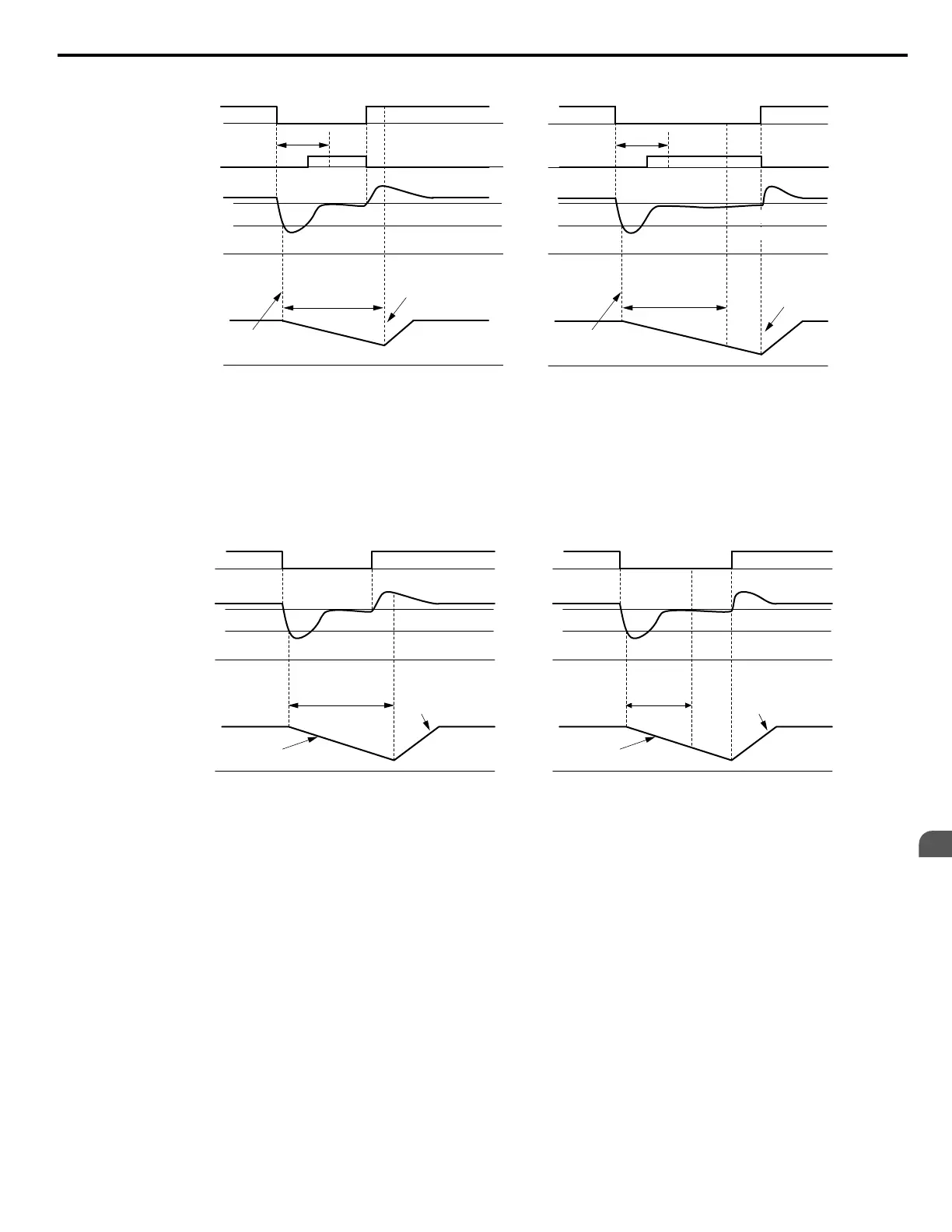
Figure 5.73 KEB Operation Using L2-02 and KEB Input
KEB Ride-Thru Operation as Long as CPU Has Power, KEB Input Not Used
Here, L2-01 = 4 and the input terminals have not been set for KEB Ride-Thru (H1-oo does not equal 65, 66, 7A, 7B). After
decelerating for the time set to parameter L2-10, the drive checks the DC bus voltage level. Deceleration continues if the DC
bus voltage is lower than the level set in L2-11. Normal operation resumes when the DC bus voltage rises above the value of
L2-11.
L2-11 (Desired DC Bus Voltage)
L2-05 (Uv Detection Level)
0 Hz
0 V
0 V
KEB Deceleration
Acceleration using L2-07 or
C1-01/03/05/07 if L2-07 = 0
Power Loss Shorter than L2-10 Power Loss Longer than L2-10
Power Loss
DC Bus Voltage
Main Power Supply
Output Frequency
L2-10
(Min. KEB Operation
Time)
L2-11 (Desired DC Bus Voltage)
L2-05 (Uv Detection Level)
0 Hz
0 V
0 V
KEB Deceleration
Acceleration using L2-07 or
C1-01/03/05/07 if L2-07 = 0
Power Loss
L2-10
(Min. KEB
Op. Time)
Figure 5.74 KEB Operation Using L2-10, Without KEB Input
KEB Ride-Thru Operation as Long as CPU Has Power, KEB Input Used
Here, L2-01 = 3 and an input terminal is set to issue KEB Ride-Thru (H1-oo = 65, 66, 7A, 7B). After decelerating for the
time set to parameter L2-10, the drive checks the DC bus voltage and the status of the digital input. Deceleration continues if
the DC bus voltage is still below the level set in L2-11 or if the digital input assigned to KEB Ride-Thru is still active. Normal
operation resumes when the DC bus voltage rises above the value of L2-11 and the terminal that initiated KEB Rid-Thru is
released.
5.8 L: Protection Functions
YASKAWA SIEP YAIP1U 01C AC Drive - P1000 Technical Manual
243
5
Parameter Details

 Loading...


