n
Alarm Outputs for Maintenance Monitors
An output can be set up to inform the user when a specific components has neared its expected performance life.
When one of multi-function digital output terminals has been assigned the maintenance monitor function (H2-oo = 2F), the
terminal will close when the cooling fan, DC bus capacitors, or DC bus pre-charge relay reach 90% of the expected performance
life, or when the IGBTs have reached 50% of their expected performance life. Additionally the digital operator will display
an alarm like shown in Table 7.5 to indicate the specific components that may need maintenance.
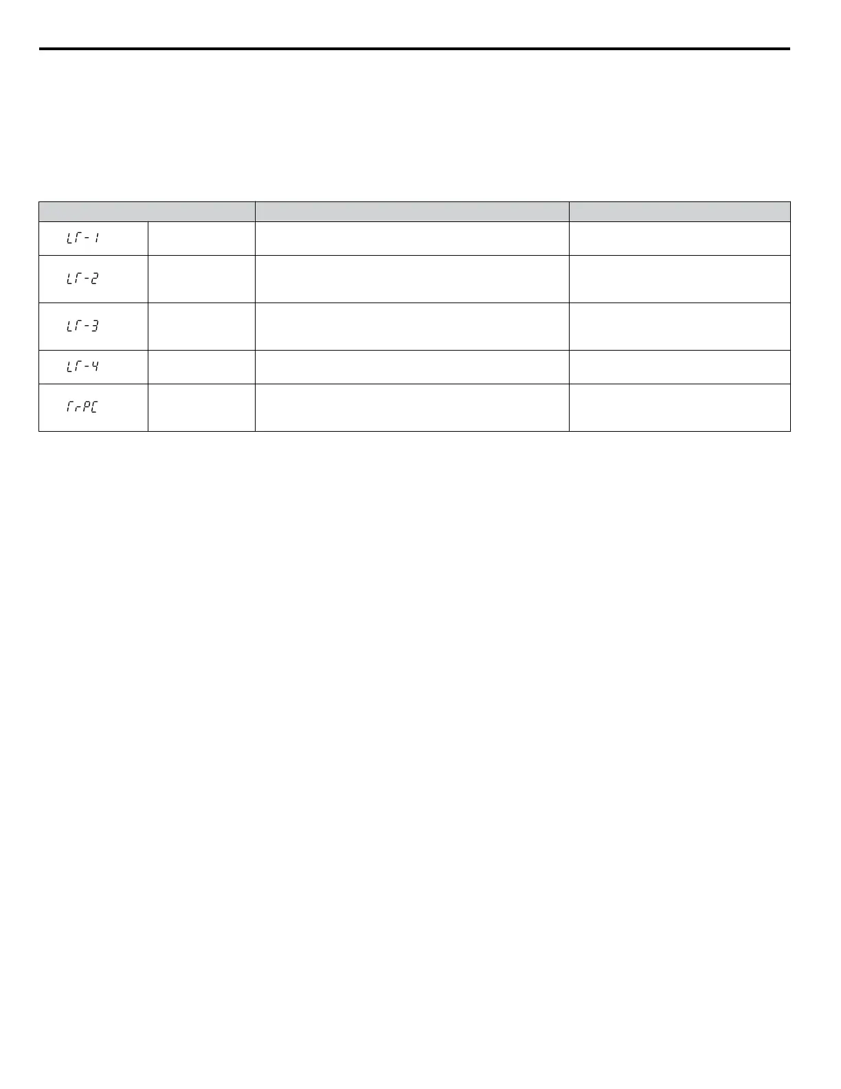
Table 7.5 Maintenance Alarms
Digital Operator Alarm Display Function Corrective Action
<1>
LT-1
The cooling fans have reached 90% of their designated
life time.
Replace the cooling fan.
<1>
LT-2
The DC bus capacitors have reached 90% of their
designated life time.
Contact a Yaskawa representative or the
nearest Yaskawa sales office on
possible drive replacement.
<1>
LT-3
The pre-charge circuit has reached 90% of its designated
life time.
Contact a Yaskawa representative or the
nearest Yaskawa sales office on
possible drive replacement.
<1>
LT-4
The IGBTs have reached 50% of their designated life
time.
Check the load, carrier frequency, and
output frequency.
<2>
TrPC
The IGBTs have reached 90% of their designated life
time.
Contact a Yaskawa representative or the
nearest Yaskawa sales office on
possible drive replacement.
<1>
This alarm message will be output only if the Maintenance Monitor function is assigned to one of the digital outputs (H2-oo = 2F). The alarm
will also trigger a digital output that is programmed for alarm indication (H2-oo = 10).
<2>
This alarm message will always be output, even if the Maintenance Monitor function is not assigned to any of the digital outputs (H2-oo = 2F).
The alarm will also trigger a digital output that is programmed for alarm indication (H2-oo = 10).
n
Related Drive Parameters
Use parameters o4-03, o4-05, o4-07, and o4-09 to reset a Maintenance Monitor to zero after replacing a specific component.
Refer to Parameter List on page 431 for details on parameter settings.
NOTICE: If these parameters are not reset after the corresponding parts have been replaced, the Maintenance Monitor function will continue
to count down the performance life from the value that was reached with the old part. If the Maintenance Monitor is not reset, the drive will
not have the correct value of the performance life for the new component.
7.3 Periodic Maintenance
344
YASKAWA SIEP YAIP1U 01C AC Drive - P1000 Technical Manual

 Loading...


