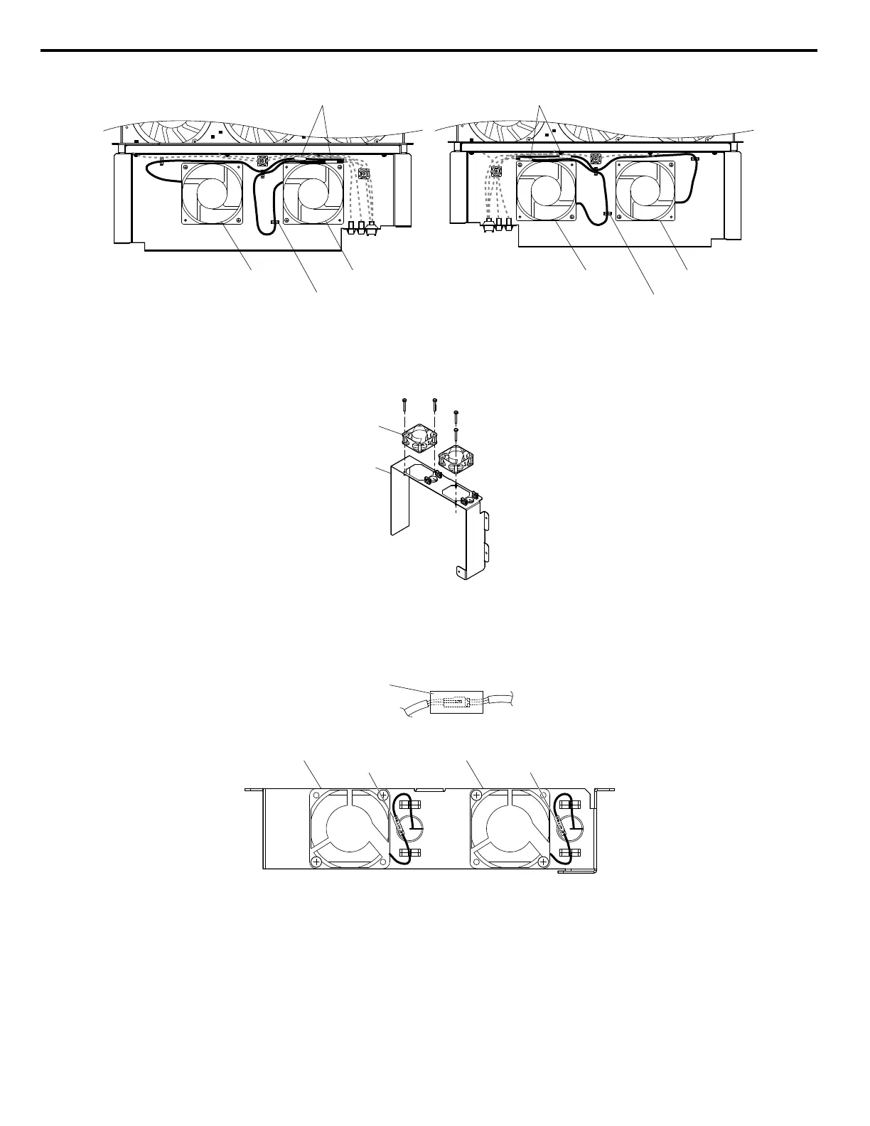
Circulation Fan B10 Circulation Fan B9
Fun Unit Case (R)
Circulation Fan B8 Circulation Fan B7
Hook
Relay Connector
Hook
Fun Unit Case (L)
Relay Connector
Figure 7.48 Cooling Fan Wiring: 4A0930 and 4A1200
9.
Replace the circuit board cooling fans.
Note: Figure 7.49 shows the right side circuit board cooling fan.
A
B
A – Circuit board cooling fan B – Circuit board cooling fan case
Figure 7.49 Fan Unit Disassembly: 4A0930 and 4A1200
10.
Position the protective tube so the fan connector sits in the center of the protective tube. (Circuit board cooling fans
only)
Protective tube
11.
Guide the lead wires through the provided hooks so the wires are held in place.
Circuit Board Cooling Fan B6 Circuit Board Cooling Fan B7
Relay Connector Relay Connector
Figure 7.50 Cooling Fan Wiring: 4A0930 and 4A1200
12.
Double-check the relay connector to ensure that it is properly connected.
n
Installing the Cooling Fan Unit
1.
Reverse the procedure described above to reinstall the cooling fan unit.
Note: Properly connect the relay connectors to the fan unit connectors.
7.4 Drive Cooling Fans
368
YASKAWA SIEP YAIP1U 01C AC Drive - P1000 Technical Manual

 Loading...


