Acquire Scans
Stratus OCT User Manual PN 2660021134133 A
3-14
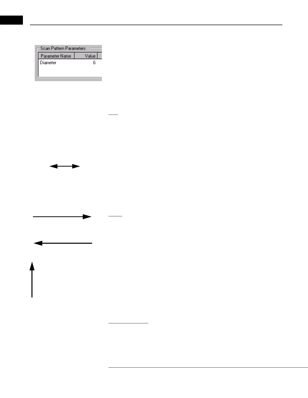
Adjust Scan Pattern Parameters
The Scan Pattern Parameter area (pictured at left) is found in the upper left of the Scan
Parameter Tab (see page 3-7). You can use it to adjust se
veral parameters including
scan size, angle or number of lines in the pattern.
• The availability of these parameters for adjustmen
t depends on the scan protocol—
see Which Scan Parameters Can Be Adjusted When on page 4-4 for
information on which you can adjust. When available, the Va
lue field has a white
background. Just click in the field and type a value. When unalterable, the Value
field has a gray background.
Size
For many scan protocols, you can adjust the size of the scan pattern, that is, the length of
line scans or the radius/diameter of circle scans.
• For size parameters, measurements are in mm. The size range of scan lines is from 3
m
m to 10 mm. The range of scan circles is from 1.5 mm to 10 mm diameter (0.75 mm
to 5 mm radius).
•
2-headed arrow
Changes the length and angle
of line scans
To adjust size, you can also move the pointer near the edge of the scan pattern until a
two-headed arrow appears (as at left), and then click and drag the arrow to adjust
t
he size (and the angle, if applicable—see below). It is easier to adjust size exactly by
typing in the new value.
• When “Radius 1" and “Radius 2" appear, Radius 1 refers to the aiming circle and
Ra
dius 2 refers to the scan acquisition circle.
Angle
0° (also 360° or -360°) Scan
proceeds from 9 to 3 o’clock.
180° or -180°. Scan proceeds
from 3 to 9 o’clock.
90° or -270°. Scan proceeds
from 6 to 12 o’clock.
For the Line scan protocol (page 4-7), you can adjust the angle of the line. The default
angle is 0° (horizontal from left to right). Compass degree measurements describe the
poi
nt of origin and the angle as seen in the video monitor. The 9 o’clock position is defined
as 0° on the compass. Degrees increase on the compass counterclockwise and decrease
clockwise. This notation style enables the user to control not only the angular position of
the line, but also its point of origin.
• Of course, this is significant when locating a point of pathology like a macular hole.
F
or example, note that a 180° line looks just like a zero degree line in a frozen video
image, but the 180° line originates at the 3 o’clock position.
• Also note that with this notation, every positive compass point has an alternative
r
epresentation 360° removed on the negative scale. For example, 180° and -180°
yield the same line with the same point of origin, as do 90° and -270°.
Number of Lines
When this field is available, you can adjust the number of lines from 6 to 24 lines.