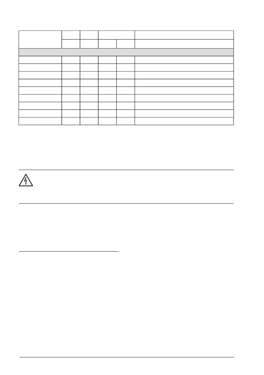
Reference resistor typesP
BRmax
R
max
R
min
ACH580-01-
hpkWohmohm
3-phase U
1
= 525…600 V, P
n
at U
n
= 575 V
Danotherm CBR-V 330 D T 406 78R UL2.091.56006002A7-6
Danotherm CBR-V 330 D T 406 78R UL2.72.24506003A9-6
Danotherm CBR-V 330 D T 406 78R UL5.44.02256006A1-6
Danotherm CBR-V 330 D T 406 78R UL7.25.41656009A0-6
Danotherm CBR-V 330 D T 406 78R UL9.97.412060011A-6
Danotherm CBR-V 330 D T 406 78R UL14.7118260017A-6
Danotherm CBR-V 560 D HT 406 39R UL21.4165625022A-6
Danotherm CBR-V 560 D HT 406 39R UL28.2214325027A-6
TBD34.9263525032A-6
Symbols
= minimum allowed brake resistor that can be connected to the brake chopperR
min
= maximum allowed brake resistor that allows P
BRmax
R
max
= maximum braking capacity of the drive, must exceed the desired braking power.P
BRmax
WARNING!
Do not use a brake resistor with a resistance below the minimum value specified
for the particular drive. The drive and the internal chopper are not able to handle
the overcurrent caused by the low resistance.
Selecting and routing the brake resistor cables
Use a shielded cable with the conductor size specified in section Terminal and entry
data for the power cables on page Terminal and entry data for the power
cables (page 278).
Minimizing electromagnetic interference
Follow these rules in order to minimize electromagnetic interference caused by the rapid
current changes in the resistor cables:
• Install the cables away from other cable routes.
• Avoid long parallel runs with other cables. The minimum parallel cabling separation
distance should be 0.3 meters.
• Cross the other cables at right angles.
• Keep the cable as short as possible in order to minimize the radiated emissions
and stress on chopper IGBTs. The longer the cable the higher the radiated emissions,
inductive load and voltage peaks over the IGBT semiconductors of the brake
chopper.
340 Resistor braking

 Loading...


