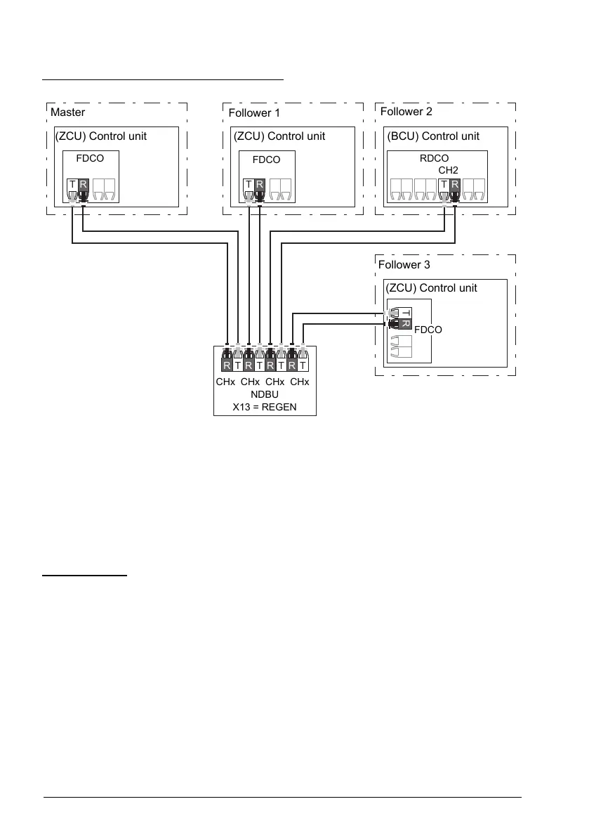
Star configuration with fiber optic cables (2)
Master
Follower 1
Follower 2
(ZCU) Control unit
(ZCU) Control unit (BCU) Control unit
FDCO
FDCO
RDCO
CH2
Follower 3
(ZCU) Control unit
FDCO
CHx CHx CHx CHx
NDBU
X13 = REGEN
Where, T = Transmitter; R = Receiver
Example parameter settings
The following is a checklist of parameters that need to be set when configuring the
master/follower link. In this example, the master broadcasts the Follower control word,
a speed reference and a torque reference. The follower returns a status word and two
actual values (this is not compulsory but is shown for clarity).
Master settings
• Master/follower link activation
•
60.1 M/F communication port (fiber optic channel or XD2D selection)
•
(60.2 M/F node address = 1)
•
60.3 M/F mode = DDCS master (for both fiber optic and wire connection)
•
60.5 M/F HW connection (Ring or Star for fiber optic, Star for wire)
• Data to be broadcast to the followers
•
61.1 M/F data 1 selection = Follower CW (Follower control word)
•
61.2 M/F data 2 selection = Used speed reference
40 Program features