■ Router mode for BCU control unit
The BCU control unit of an inverter unit can be set to a “router mode” to allow the control
of locally-connected power units (for example, inverter modules) by another BCU. Using
the router mode and some hardware switching, it is possible to have the same modules
alternate between inverter and, for example, IGBT supply use.
The router mode involves connecting the two BCUs together by their PSL2 channels.
When router mode is active, the channels coming from the other BCU are forwarded to
the local modules.
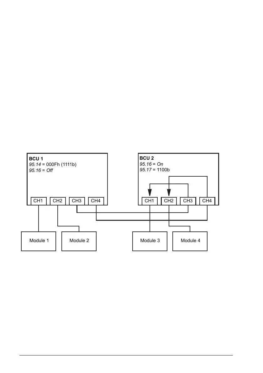
The diagrams below show how the control of four converter modules can be switched
between two BCUs.
Note: For an example of how to switch converter modules between inverter and IGBT
supply use, see the ACS880 IGBT supply control program firmware manual
(3AUA0000131562 [English]).
BCU 1 controlling all modules, BCU 2 in router mode
BCU 1
95.14 = 000Fh (1111b)
95.16 = Off
BCU 2
95.16 = On
95.17 = 1100b
CH1 CH2 CH3 CH4 CH1 CH2 CH3 CH4
Module 1
Module 2
Module 3 Module 4
BCU 2 controlling all modules, BCU 1 in router mode
108 Program features