Commissioning
98
1SVC 440 795 M1100
Configuring the interface
for the COM-LINK mode
If you wish to set up point-to-point communication with
another station, this can be done using either the serial
interface or CL-NET. The display system must be provided
with a display and operating unit. The connection must be
configured for this purpose (a section “Introduction to
COM-LINK”, page 334).
Proceed as follows:
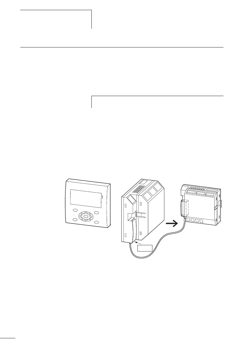
X Connect both stations together.
Use only the original connection cables. The connector
marked POW-Side must be plugged into a display system.
The display system feeds the interface electronics of the
connection line at both ends.
X Connect the power supply to both stations.
Figure: 73: Example with both COM stations.
The display base module with the program is the active station and
the second station is then the remote station.
X Switch on the power supply for both stations.
X Ensure that both stations have a power supply. The POW
LED must light up or flash. It is only possible to configure
the stations which have an active power supply.
h
Ensure that the other station supports the COM-LINK mode.
POW-Side