Display system operation
125
1SVC 440 795 M1100
The coil functions and parameters for the function blocks are
explained with the description of each function block.
Markers, analog operands
Specific markers are available for actively addressing values
or inputs/outputs.
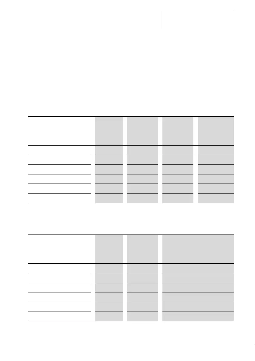
Table 8: Markers
The following data accesses can be made to the slave in
COM communication mode. Note the REMOTE MARKER
setting in the following table.
The following rules apply if you want to use selective binary
operands (contacts) from the markers MD, MW, MB:
Markers
Analog operand
Display
system
display
Number Value range Access type
r = Read
w = Write
Marker 32 bit MD 01…96 32 bit r, w
Marker 16 bit MW 01…96 16 bit r, w
Marker 8 bit
MB 01…96 8 bit r, w
Marker 1 bit M 1…96 1 bit r, w
Analog inputs display system IA X X=01…04 10 bit r
Analog output QA X X=01 10 bit r, w
Markers
Analog operand
Display
system
display
Number Value range Access type
r = Read
w = Write
Marker 32 bit 1MD 01…20 32 bit r, w
Marker 16 bit 1MW 01…40 16 bit r, w
Marker 8 bit 1MB 01…80 8 bit r, w
Marker 1 bit 1M 1…96 1 bit r, w
Analog inputs display system 1IA X X=01…04 10-bit r
Analog output 1QA X X=01 10 bit r