Connecting inputs
51
1SVC 440 795 M1100
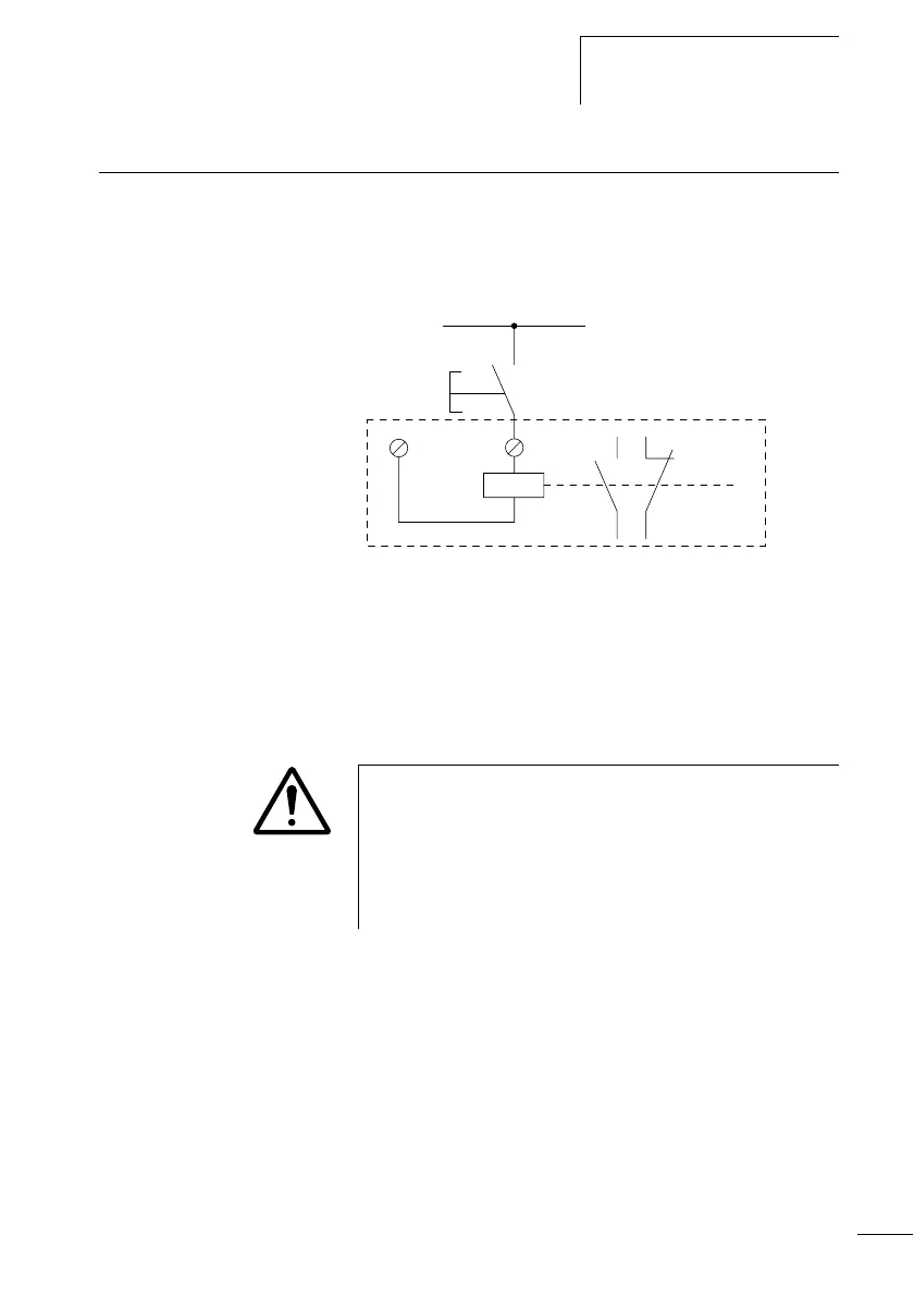
Connecting inputs The inputs of the logic relay or display system switch
electronically. Once you have connected a contact via an
input terminal, you can reuse it as a contact in the display
system circuit diagram as often as you like.
Figure: 33: Connecting inputs
Connect contacts to the input terminals of the logic relay or
display system, e.g. pushbutton actuators or switches
Connecting AC display I/O modules
+24 V
S1
0 V
I1
I1 i1
L
N
Caution!
Connect the inputs for AC in accordance with the safety
regulations of VDE, IEC, UL and CSA with the same phase
conductor that provides the power supply voltage.
Otherwise the device will not detect the switching signal
or may be destroyed by the overvoltage.