Wiring with the display system
188
1SVC 440 795 M1100
Wiring of a frequency counter
You integrate a frequency counter into your circuit in the
form of a contact and coil. The counter relay has different
coils and contacts.
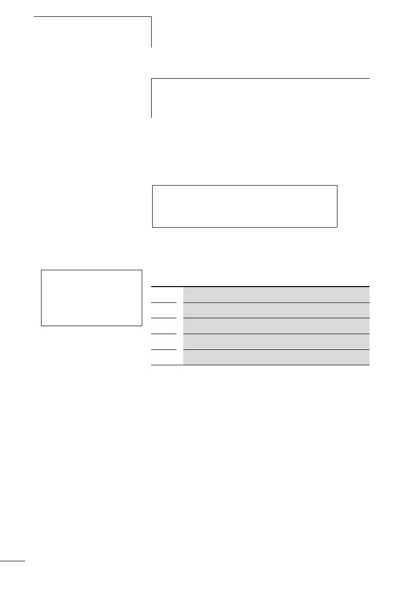
Figure: 101: Display system circuit diagram with frequency
counter
Parameter display and parameter set for frequency counter:
In the parameter display of a counter relay you change
setpoint values and/or the preset value and the enable of the
parameter display.
Value range
The function block operates in the integer range from 0 to
5000
1 kHz = 1000
Behaviour when value range is exceeded
The value range cannot be exceeded as the maximum
measured value is less than the value range.
Inputs
The function block inputs
>SH and >SL can have the
following operands:
h
Avoid unforeseeable switch states. Only use each coil of a
relay once in the circuit diagram. Use a counter input for
the CF, CH, CI counters only once.
I 05---------------------------Ä CF01EN
CF01OF-------------------------Ä Q 01
CF01FB-------------------------Ä Q 02
CF01ZE-------------------------Ä q 03
CF01 -
>SH
>SL
QV>
CF01 Frequency counter function block number 01
- Does not appear in the parameter display
>SH Upper setpoint
>SL Lower setpoint
QV> Actual value in RUN mode