Wiring with the display system
240
1SVC 440 795 M1100
Contacts
PT01Q1 to PT32Q1: State of the trigger coil
Coils
PT01T to PT32T: Trigger coils
Memory requirement of the PUT function block
The PUT function block requires 36 bytes of memory plus 4
bytes per constant at the function block input.
PUT diagnostics
The PUT function block only functions if the CL-NET network
is running properly (a section “Signs of life of the
individual stations and diagnostics”, page 331).
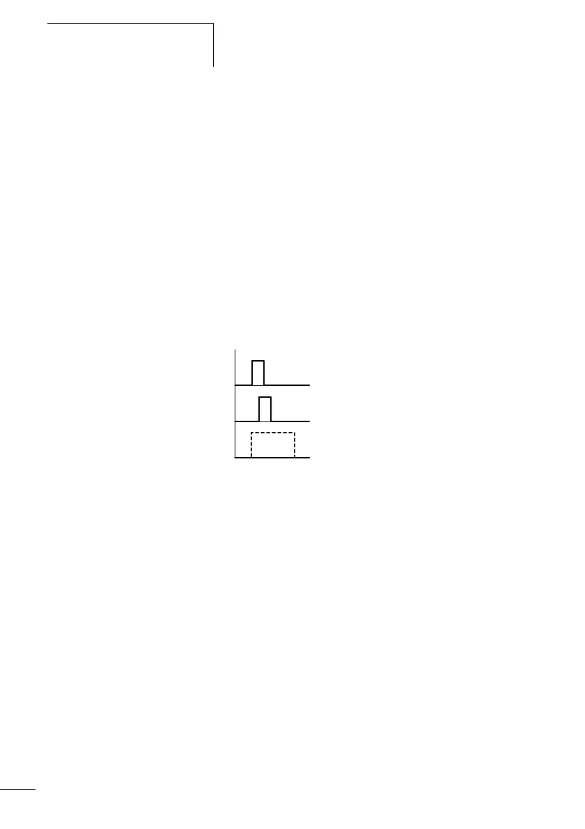
Function of the PUT function block
Figure: 126: Operational diagram PUT module
1: Trigger coil
2: Trigger coil contact feedback
3: Send
Pulse width modulation
The display system provides 2 pulse width modulation
function blocks PW01 and PW02. The function blocks are
connected directly to the outputs.
They are assigned as follows:
PW01 r Q1
PW02 r Q2
1
2
3