Connecting outputs
61
1SVC 440 795 M1100
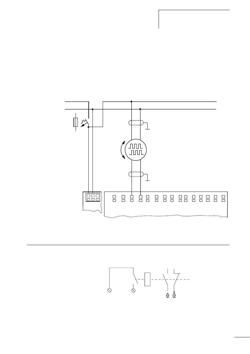
Connecting incremental encoders
Inputs I1, I2 and I3, I4 on the display system can each be
used for the high-speed counting of an incremental encoder
independently of the cycle time. The incremental encoder
must generate two 24 V DC square wave signals with a 90°
phase shift between them.
Figure: 44: Connecting incremental encoders
Connecting outputs The Q… outputs function inside the display system as
isolated contacts.
Figure: 45: Output Q
L01–
> 1 A
L01+
I1 I3 I4 I7 I8 I9 I10
L02+
AB
I2 I5 I6 I11
I12
+24V 0V 0V
Q1
12