Commissioning
92
1SVC 440 795 M1100
Configuring a CL-NET
network
If you want to work with the CL-NET network and
communicate with several stations, the network must be
configured first.
Proceed as follows:
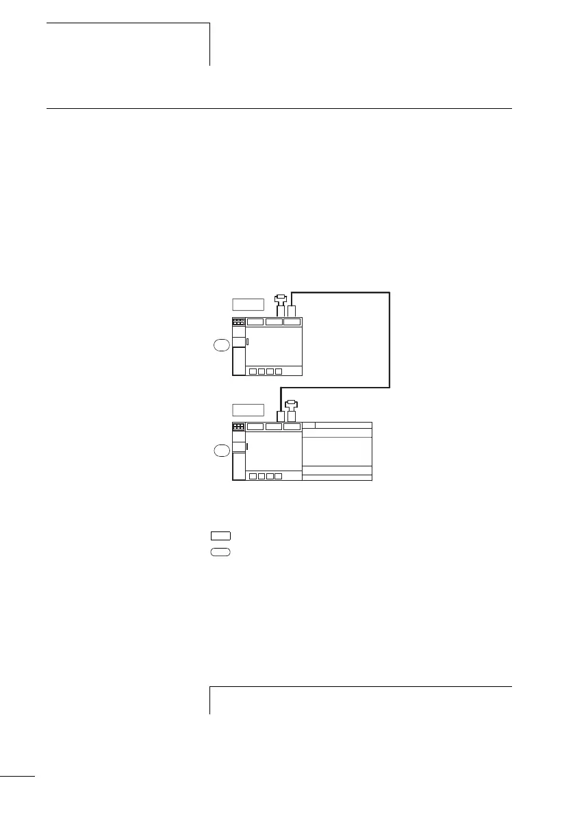
X Interconnect all network stations. CL-NET socket 2e to
CL-NET socket 1L.
X The first station 1 (socket 1L) and last station (socket 2e)
requires a network terminating resistor a.
X Connect the power supply to all stations.
Figure: 72: Example topology with two CL-NET stations
a Network terminating resistor
Physical location
station number
X Switch on the power supply for all stations.
X Ensure that all stations have a power supply. The POW
LED must light up or flash. It is only possible to configure
the stations which have an active power supply.
X Proceed to the first physical station (Location 1). This
station has the termination resistor inserted on socket 1.
2
1
1
2
R1 – R12
S1 – S8
h
The following tasks are only possible in STOP mode.