Function blocks
245
1SVC 440 795 M1100
Accuracy of time synchronisation
The maximum time deviation between the functional
stations is 5 s.
Set cycle time
The display system provides one set cycle time function block
ST01. The set cycle time function block is a supplementary
function block for the PID controller.
The set cycle time function block provides a fixed cycle time
for processing the circuit diagram and the function blocks.
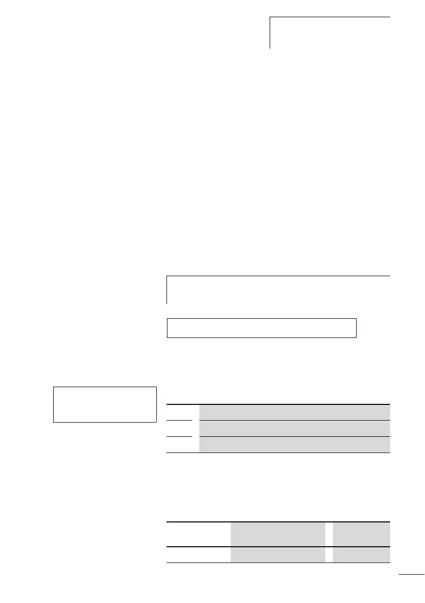
Wiring a set cycle time function block
The ST set cycle time function block is integrated in the
circuit diagram as a coil.
Figure: 129: Display system circuit diagram with enabling of set
cycle time function block.
Parameter display for set cycle time:
The parameter display is used to modify the set cycle time,
the minimum on time and the enabling of the parameter
display.
Time range
h
To prevent unpredictable switching states, use each coil of
a relay once only in the circuit diagram.
-------------------------------Ä ST01EN
ST01 +
>I1
ST01 Set cycle time function block number 01
+ Appears in the parameter display
>I1 Set cycle time
Parameter
Value and time range Resolution
I1 0 to 1000 ms