Function blocks
241
1SVC 440 795 M1100
The pulse width modulation function block is primarily used for
outputting the manipulated variable of a PID controller. The
maximum frequency is 200 Hz. This corresponds to a period
duration of 5 ms. The maximum period duration is 65.5 s.
Wiring a pulse width modulation function block
A pulse width modulation function block is integrated in the
circuit diagram as a contact or coil.
Figure: 127: Display system circuit diagram with pulse width
modulation
Parameter display and parameter set for pulse width
modulation:
The parameter display for a timing relay is used to modify the
period duration, the minimum on time and the enabling of
the parameter display.
h
When using the pulse width modulation function block
with a minimum on time of less than 1 s only use devices
with transistor outputs.
h
To prevent unpredictable switching states, use each coil of
a relay once only in the circuit diagram.
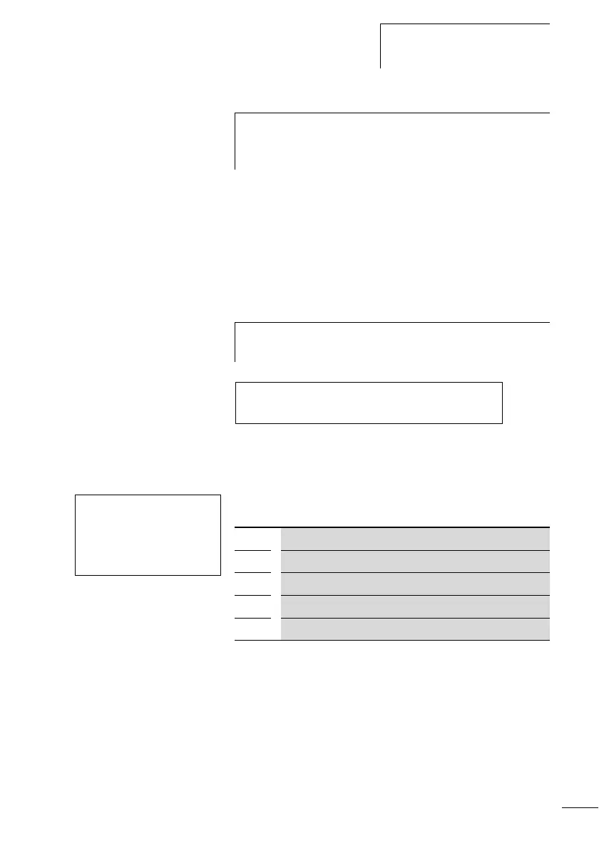
M 95---------------------------Ä PW01EN
PW01E1-------------------------Ä M 96
PW02 +
>SV
>PD
>ME
PW02 Pulse width modulation function block number 02
+ Appears in the parameter display
>SV Manipulated variable input
>PD Period duration in ms
>ME Minimum on duration, minimum off duration in ms