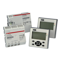
Wiring with the display system
204
1SVC 440 795 M1100
Contacts
DB01Q1 to DB32Q1
Contact (N/O contact) DB…Q1 switches to status 1 if the
trigger signal is set to 1.
Coils
DB01T_ to DB32T_, acceptance of the value at >I1 with a
rising edge.
Memory requirement of the data function block
The data block function block requires 36 bytes of memory
plus 4 bytes per constant at the function block input.
Retention
Data function blocks can be operated with retentive actual
values. The quantity can be selected in the SYSTEM r
RETENTION menu.
Function of the data function block
Figure: 109: Signal diagram of data function block
1: Value at input >I1
2: Trigger coil DB…T_
3: Value on DB…QV>
2
3
1
h
The value at input >I1 is only transferred with a rising
trigger edge to an operand (e.g.: MD42, QA01) on output
QV>. Output QV retains its value until it is overwritten.

 Loading...