Wiring with the display system
252
1SVC 440 795 M1100
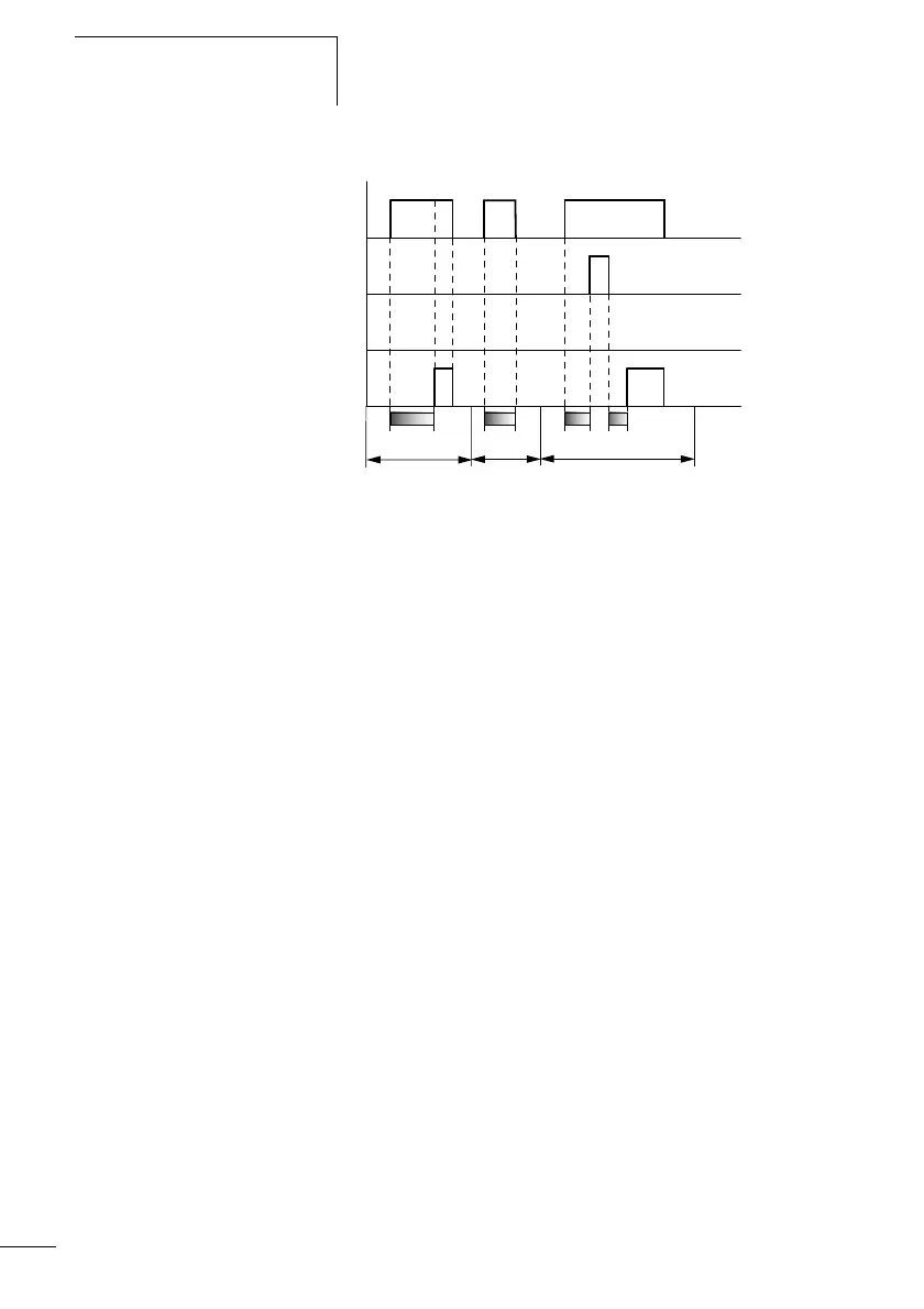
Figure: 131: Signal diagram of timing relay, on-delayed
(with and without random switching)
1: Trigger coil T…EN
2: Stop coil T…ST
3: Reset coil T…RE
4: Switching contact (N/O contact) T…Q1
t
s
: Setpoint time
•Range A:
The set time elapses normally.
•Range B:
The entered setpoint does not elapse normally because the
trigger coil drops out prematurely.
•Range C:
The stop coil stops the time from elapsing.
t
1
+ t
2
= t
s
t
A
B
t
s
1
2
4
3
C

 Loading...


